25
English
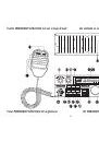
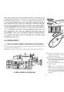
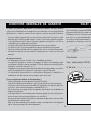
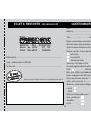
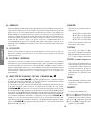
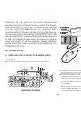
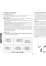
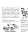
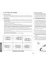
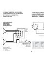
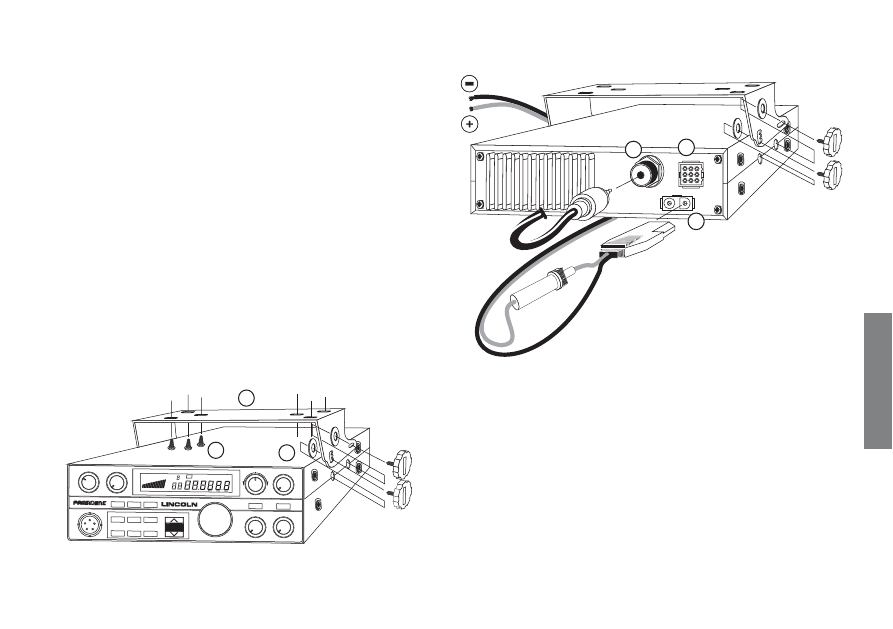
MOUNTING DIAGRAM
Welcome to the world of the most sophisticated
microprocessor controlled Amateur radios. This entirely
new generation of PRESIDENT Amateur Radio will give
you the most complete access to amateur radio
communication. Introducing state-of-the-art technology
for the most advanced features, this PRESIDENT LINCOLN
is a new milestone in user friendliness and prompt response
to the most demanding amateur. To assure you get the
most enjoyment of all the features, please read this
guide thoroughly before installing and operating your
PRESIDENT LINCOLN.
A) INSTALLATION :
1) WHERE AND HOW TO MOUNT YOUR MOBILE RADIO :
a)
You should choose the most appropriate setting from a simple and practical
point of view.
b)
Your radio should not interfere with the driver or the passengers.
c)
Remember to provide for the passing and protection of different wires (e.g.
power, antenna, accessory cabling) so that they do not in any way interfere
with the driving of the vehicle.
d)
To install your equipment, use the cradle (
1
) and the self-tapping screws [
2
]
provided (drilling diameter 3.2 mm). Take care not to damage the vehicle’s
electrical system while drilling the dash board.
e)
Choose where to place the microphone support and remember that the
microphone cord must stretch to the driver without interfering with the controls
of the vehicle.
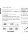
- N.B. :
As the transceiver has a frontal microphone socket, it can be set into the
dash board. In this case, you will need to add an external loud speaker to
improve the sound quality of communications (connector (
C
) situated on the
back panel). Ask your dealer for advice on mounting your radio.
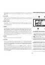
Noir/Negro
Black/Schwarz
Rouge/Rojo
Red/Rot
A
B
C
1
2
3
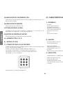
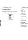
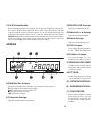
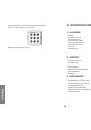
VOLUME
INDIC
METER
CHANNEL
FREQUENCY
PA
NB
OFF
SQUELCH
LOC/DX
MIC GAIN
AUTO SQ
RF POWER
SWR/CAL
RIT
+
-
USB
LSB
CW
AM
FM
1
1
RF
MOD
1,5
2
3
3
5
7 9
SPAN
CHANNEL
F.LOCK
SCAN
BAND
DIM
BEEP
TX
SWR
▲