6
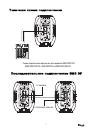
SMS12DP700
CLIP
MIC LEVEL
MIN
MAX
LINE LEVEL
MIN
MAX
VOLUME
MIN
MAX
-12
TREBLE
+12
BASS
-12
+12
POWER
LINE
OUTPUT
MIC
INPUT
R
L
LINE INPUT
HF:1.35 80W (34mm Ti dome drive)
"
"
LF:12 300W (60mm voice coil/50 oz magnet)
ACTIVE SOUND REINFORCEMENT SYSTEM
Internal Switch Mode Power Supply(SMPS)
Revolutionary Class-D Amplifier Technology
Nominal Impedance: 8 ohm
AC 230V 50Hz
POWER
GROUND
1
2
3
4
2
5
5
5
6
6
7
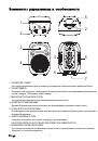
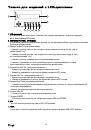
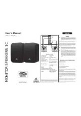
Controls and Features
bolt to prevent the speaker from shifting during use.
USB
MMC
SD
PLAY VOL+ VOL-
EQ
SD POWER
PAUSE NEXT PREV
PRT
USB
STOP
POWER
GRO
SMS15DP760LCD
HF:1.75 80W (44mm
"
"
LF:15 300W (75mm vo
ACTIVE SOUND REINF
Internal Switch Mode P
Revolutionary Class-D
Nominal Impedance: 8
MIC LEVEL
MIN
MAX
LINE LEVEL
LINE
OUTPUT
MIC
INPUT
R
L
LINE INPUT
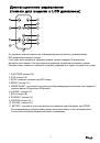
SMS15DP760LCD REAR PANEL DESCRIPTION
1
2
3
4
5
6
9
10
16
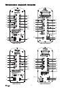
1. Mic XLR Input - Plug a mic directly into this port for public address
usage and let your voice be heard.
2. 1/4
”
MIC Input
–
Plug a mic directly into this port.
3. Balanced RCA Li ne Input
–
This connection is designed to accept
a balanced line input signal from a mixeror other line level device
with a balanced output jack. Use a balanced cable when the signal
cable length exceeds 15 feet, this will reduce excessive signal loss.
Be sure to connect only line level input devices such as mixers
and tape machines to this jack.
4. Balanced XLR Li ne Input
–
This connection is designed to
other line level
able when
the signal cable length exceeds 15 feet, this will reduce excessive
This jack is used to send
the incoming line level signal from either of the Line Level Inputs
3
8
6. XLR LINE Output
r powered
speaker.
7.Main Power Inlet
–
ble power
cord.
8.Fuse Holder
–
Th
t same type
fuse, unless other
9. Microphone input V
eaker.
10. Line level input v
nected to
the Line Level Inp
11. output volume
–
er.
12. Treble control
–
e maximum
amount of treble g
e knob in a
counter-clockwise d
e knob in a
clockwise directio
13. Bass Control
–
output signal. The m
e is -12dB.
Turning the knob i
nnel signal,
turning the knob in a c
l signal.
14. Power indica tor led - L
15. Clip Led - If this LED i
ower the volume
to the point where the L
16. AC VOLTOLTOLTA
erating voltage.
Operating voltage ca
s set to the proper
voltage for your area b
ff before change
the position of the Vo
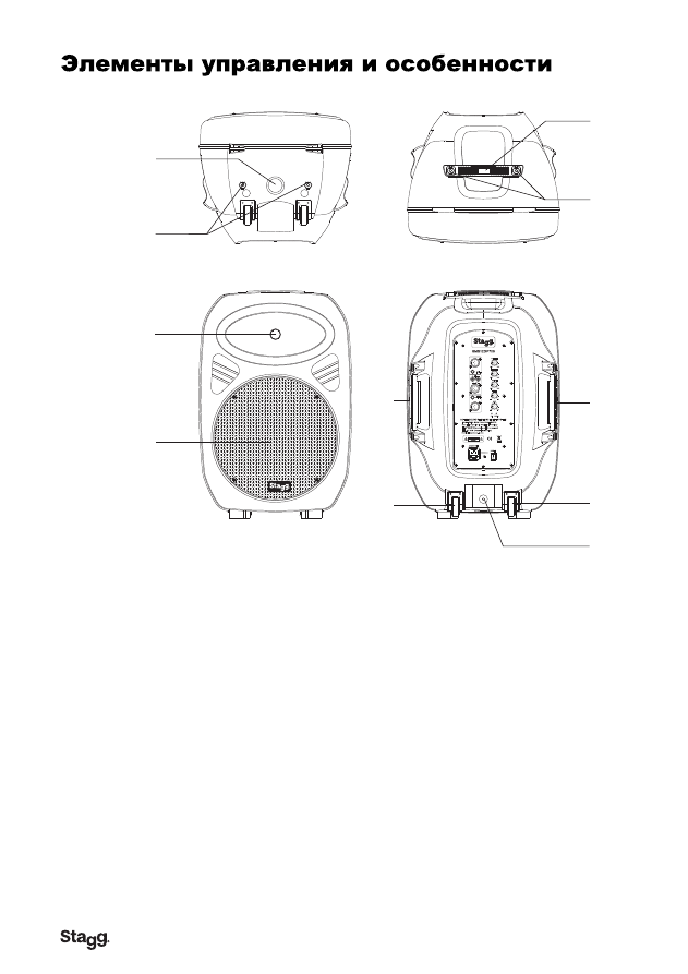
1. ГНЕЗДО ДЛЯ СТОЙКИ
Это гнездо предназначено для установки на стандартные стойки или треноги диаметром 25 мм.
2. ТОЧКИ ПОДВЕСА
В колонках этой серии есть точки подвеса. Их можно использовать для подвешивания акустических
систем в воздухе. Соблюдайте схемы подвеса.
3. ВЫСОКОЧАСТОТНЫЙ ИЗЛУЧАТЕЛЬ
Это устройство используется для воспроизведения высоких частот.
4. НИЗКОЧАСТОТНЫЙ ДИНАМИК
Динамик большой мощности используется для воспроизведения средних и низких частот.
5. РУЧКИ ДЛЯ ТРАНСПОРТИРОВКИ
В этой серии колонок предусмотрены надежные ручки для переноски. Используйте их для простой и
безопасной переноски.
6. КОЛЕСА БАГАЖНОГО ТИПА
позволяют легко катить или толкать колонку при транспортировке.
НЕ ИСПОЛЬЗУЙТЕ ИХ НА СТУПЕНЯХ ИЛИ РЕБРИСТЫХ ПОВЕРХНОСТЯХ.
7. БЛОКИРОВКА ГНЕЗДА ДЛЯ СТОЙКИ
Этот штырь используется для фиксации колонки на месте при креплении на стойку или подставку.
Убедитесь, что он прочно закреплен.