8
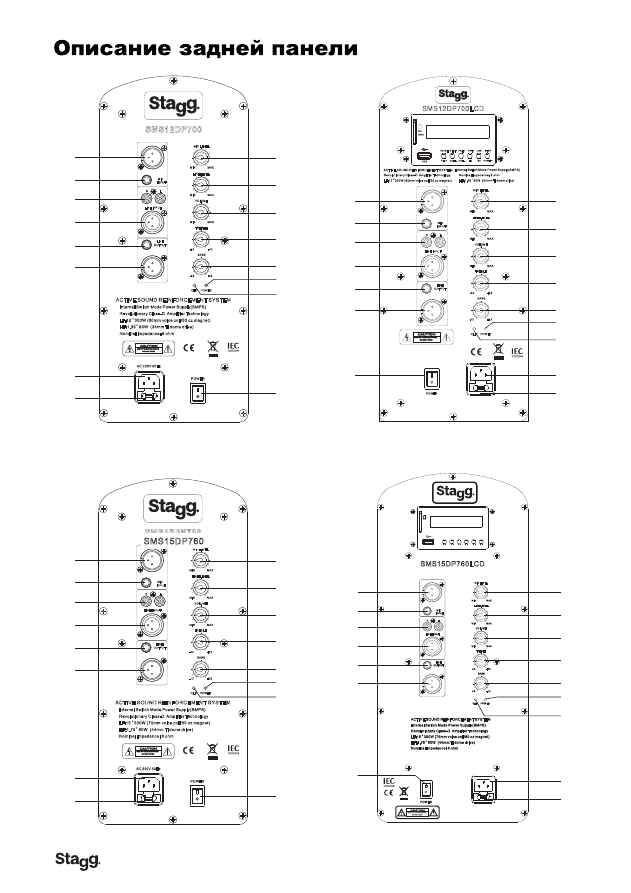
SMS15DP700 REAR PANEL DESCRIPTION
6. XLR LINE Output
–
Using a XLR cable, use this port to daisy chain from your this speaker to other
powered speaker.
7.Main Power Inlet
–
This connector is used to supply main power to the unit via the included detachable
power cord.
8.Fuse Holder
–
This housing stores the 3.15 amp GMA protective fuse. Always replace with the exact
same type fuse, unless otherwise instructed,
9. Microphone input Volume
–
This knob is used to increase or decrease the volume output on your
speaker.
10. Line level input volume
–
This knob is used to regulate the output signal of the line level source
connected to the Line Level Inputs.
11. output volume
–
This knob is used to regulate the output signal being sent to other powered speaker.
12. Treble control
–
This knob is used to regulate the amount treble applied to the output signal. The
maximum amount of treble gain is +12dB and the maximum amount of treble decrease is -12dB.
Turning the knob in a counter-clockwise direction will decrease the amount of treble applied to a
channel signal, turning the knob in a clockwise direction will increase the amount of treble applied to
a channel signal.
13. Bass Control
–
This knob is used to regulate the amount bass applied to the output signal. The
maximum amount of bass gain is +12dB and the maximum amount of bass decrease is -12dB. Turning
the knob in a counter-clockwise direction will decrease the amount of bass applied to a channel signal,
turning the knob in a clockwise direction will increase the amount of bass applied to a channel signal.
14. Power indica tor led - LED lights up to indicate the speaker is on.
15. Clip Led - If this LED is lit it means your signal is clipping. To stop the signal from clipping lower
the volume to the point where the LED is blinking along with the bass beat.
16. AC VOLTOLTOLTAGEGE SELEELEELECTOTOR - This switch is used to change the operating
voltage. Operating voltage can be toggled between 115v or 230v/50~60Hz. Be sure the selector is
set to the proper voltage for your area before attempting to operate the unit. Always be sure main
power is shut off before change the position of the Voltage Selector Switch.
SMS15DP700
CLIP
MIC LEVEL
MIN
MAX
LINE LEVEL
MIN
MAX
VOLUME
MIN
MAX
-12
TREBLE
+12
BASS
-12
+12
POWER
LINE
OUTPUT
MIC
INPUT
R
L
LINE INPUT
HF:1.75 80W (44mm Ti dome drive)
"
"
LF:15 300W (70mm voice coil/60 oz magnet)
ACTIVE SOUND REINFORCEMENT SYSTEM
Internal Switch Mode Power Supply(SMPS)
Revolutionary Class-D Amplifier Technology
Nominal Impedance: 8 ohm
AC 230V 50Hz
POWER
GROUND
1
2
3
4
5
6
7
9
10
11
12
13
15
16
8
14
1. Mic XLR Input - Plug a mic directly into
this port for public address usage and let
your voice be heard.
2. 1/4
”
MIC Input
–
Plug a mic directly in
to this port.
3. Balanced RCA Li ne Input
–
This connection
is designed to accept a balanced line input
signal from a mixer or other line level device
with a balanced output jack. Use a balanced
cable when the signal cable length exceeds
15 feet, this will reduce excessive signal loss.
Be sure to connect only line level input devices
such as mixers and tape machines to this jack.
4. Balanced XLR Li ne Input
–
This connection
is designed to accept a balanced line input signal
from a mixer or other line level device with
a balanced output jack. Use a balanced
cable when the signal cable length exceeds
15 feet, this will reduce excessive signal loss.
5.1/4
”
Line Output Jack
–
This jack is used
to send the incoming line level signal from
either of the Line Level Inputs Jacks to other
powered speaker.
SMS12DP700LCD REAR PANEL DESCRIPTION
6. XLR LINE Output
–
Using a XLR cable, use this port to daisy chain from your this speaker to other powered
speaker.
7.Main Power Inlet
–
This connector is used to supply main power to the unit via the included detachable power
cord.
8.Fuse Holder
–
This housing stores the 3.15 amp GMA protective fuse. Always replace with the exact same type
fuse, unless otherwise instructed,
9. Microphone input Volume
–
This knob is used to increase or decrease the volume output on your speaker.
10. Line level input volume
–
This knob is used to regulate the output signal of the line level source connected
to the Line Level Inputs.
11. output volume
–
This knob is used to regulate the output signal being sent to other powered speaker.
12. Treble control
–
This knob is used to regulate the amount treble applied to the output signal. The maximum
amount of treble gain is +12dB and the maximum amount of treble decrease is -12dB. Turning the knob in a
counter-clockwise direction will decrease the amount of treble applied to a channel signal, turning the knob in a
clockwise direction will increase the amount of treble applied to a channel signal.
13. Bass Control
–
This knob is used to regulate the amount bass applied to the output signal. The maximum
amount of bass gain is +12dB and the maximum amount of bass decrease is -12dB. Turning the knob in a
counter-clockwise direction will decrease the amount of bass applied to a channel signal, turning the knob in a
clockwise direction will increase the amount of bass applied to a channel signal.
14. Power indica tor led - LED lights up to indicate the speaker is on.
15. Clip Led - If this LED is lit it means your signal is clipping. To stop the signal from clipping lower the volume to
the point where the LED is blinking along with the bass beat.
16. AC VOLTOLTOLTAGEGE SELEELEELECTOTOR - This switch is used to change the operating voltage. Operating
voltage can be toggled between 115v or 230v/50~60Hz. Be sure the selector is set to the proper voltage for your
area before attempting to operate the unit. Always be sure main power is shut off before change the position
of the Voltage Selector Switch.
1
2
3
4
5
6
7
9
10
11
12
13
15
16
8
14
1. Mic XLR Input - Plug a mic directly into this port for public
address usage and let your voice be heard.
2. 1/4
”
MIC Input
–
Plug a mic directly into this port.
3. Balanced RCA Li ne Input
–
This connection is designed to
accept a balanced line input signal from a mixer or other line
level device with a balanced output jack. Use a balanced
cable when the signal cable length exceeds 15 feet, this will
reduce excessive signal loss. Be sure to connect only line level
input devices such as mixers and tape machines to this jack.
4. Balanced XLR Li ne Input
–
This connection is designed to
accept a balanced line input signal from a mixer or other line level
device with a balanced output jack. Use a balanced cable when
the signal cable length exceeds 15 feet, this will reduce excessive
signal loss.
5.1/4
”
Line Output Jack
–
This jack is used to send the incoming
line level signal from either of the Line Level Inputs Jacks to
other powered speaker.
SMS12DP700LCD
CLIP
MIC LEVEL
MIN
MAX
LINE LEVEL
MIN
MAX
VOLUME
MIN
MAX
-12
TREBLE
+12
BASS
-12
+12
POWER
LINE
OUTPUT
MIC
INPUT
R
L
LINE
INPUT
HF:1.35 80W (34mm Ti dome drive)
"
"
LF:12 300W (60mm voice coil/50 oz magnet)
ACTIVE SOUND REINFORCEMENT SYSTEM Internal Switch Mode Power Supply(SMPS)
Revolutionary Class-D Amplifier Technology
Nominal Impedance: 8 ohm
AC 230V 50Hz
POWER
GROUND
USB
MMC
SD
PLAY VOL+ VOL-
EQ
SD POWER
PAUSE NEXT PREV
PRT
USB
STOP
5
6
SMS12DP700 REAR PANEL DESCRIPTION
6. XLR LINE Output
–
Using a XLR cable, use this port to daisy chain from your this speaker to other powered
speaker.
7.Main Power Inlet
–
This connector is used to supply main power to the unit via the included detachable power cord.
8.Fuse Holder
–
This housing stores the 3.15 amp GMA protective fuse. Always replace with the exact same type
fuse, unless otherwise instructed,
9. Microphone input Volume
–
This knob is used to increase or decrease the volume output on your speaker.
10. Line level input volume
–
This knob is used to regulate the output signal of the line level source connected to
the Line Level Inputs.
11. output volume
–
This knob is used to regulate the output signal being sent to other powered speaker.
12. Treble control
–
This knob is used to regulate the amount treble applied to the output signal. The maximum
amount of treble gain is +12dB and the maximum amount of treble decrease is -12dB. Turning the knob in a
counter-clockwise direction will decrease the amount of treble applied to a channel signal, turning the knob in a
clockwise direction will increase the amount of treble applied to a channel signal.
13. Bass Control
–
This knob is used to regulate the amount bass applied to the output signal. The maximum
amount of bass gain is +12dB and the maximum amount of bass decrease is -12dB. Turning the knob in a
counter-clockwise direction will decrease the amount of bass applied to a channel signal, turning the knob in a
clockwise direction will increase the amount of bass applied to a channel signal.
14. Power indica tor led - LED lights up to indicate the speaker is on.
15. Clip Led - If this LED is lit it means your signal is clipping. To stop the signal from clipping lower the volume to
the point where the LED is blinking along with the bass beat.
16. AC VOLTOLTOLTAGEGE SELEELEELECTOTOR - This switch is used to change the operating voltage.
Operating voltage can be toggled between 115v or 230v/50~60Hz. Be sure the selector is set to the proper voltage
for your area before attempting to operate the unit. Always be sure main power is shut off before change the position
of the Voltage Selector Switch.
SMS12DP700
CLIP
MIC LEVEL
MIN
MAX
LINE LEVEL
MIN
MAX
VOLUME
MIN
MAX
-12
TREBLE
+12
BASS
-12
+12
POWER
LINE
OUTPUT
MIC
INPUT
R
L
LINE INPUT
HF:1.35 80W (34mm Ti dome drive)
"
"
LF:12 300W (60mm voice coil/50 oz magnet)
ACTIVE SOUND REINFORCEMENT SYSTEM
Internal Switch Mode Power Supply(SMPS)
Revolutionary Class-D Amplifier Technology
Nominal Impedance: 8 ohm
AC 230V 50Hz
POWER
GROUND
1
2
3
4
5
6
7
9
10
11
12
13
15
16
8
14
1. Mic XLR Input - Plug a mic directly into this port for public
address usage and let your voice be heard.
2. 1/4
”
MIC Input
–
Plug a mic directly into this port.
3. Balanced RCA Li ne Input
–
This connection is designed
to accept a balanced line input signal from a mixer
or
other
line level device with a balanced output jack. Use a balanced
cable when the signal cable length exceeds 15 feet, this will
reduce excessive signal loss. Be sure to connect only line level
input devices such as mixers and tape machines to this jack.
4. Balanced XLR Li ne Input
–
This connection is designed to
accept a
balanced line input signal from a mixer or other line
level device with a balanced output jack. Use a balanced
cable when the signal cable length exceeds 15 feet, this will
reduce excessive signal loss.
5.1/4
”
Line Output Jack
–
This jack is used to send the
incoming line level signal from either of the Line Level
Inputs Jacks to other powered speaker.
SMS12DP700LCD REAR PANEL DESCRIPTION
6. XLR LINE Output
–
Using a XLR cable, use this port to daisy chain from your this speaker to
other powered speaker.
7.Main Power Inlet
–
This connector is used to supply main power to the unit via the included
detachable power cord.
8.Fuse Holder
–
This housing stores the 3.15 amp GMA protective fuse. Always replace with the
exact same type fuse, unless otherwise instructed,
9. Microphone input Volume
–
This knob is used to increase or decrease the volume output on your
speaker.
10. Line level input volume
–
This knob is used to regulate the output signal of the line level source
connected to the Line Level Inputs.
11. output volume
–
This knob is used to regulate the output signal being sent to other powered
speaker.
12. Treble control
–
This knob is used to regulate the amount treble applied to the output signal.
The maximum amount of treble gain is +12dB and the maximum amount of treble decrease is
-12dB. Turning the knob in a counter-clockwise direction will decrease the amount of treble applied
to a channel signal, turning the knob in a clockwise direction will increase the amount of treble
applied to a channel signal.
13. Bass Control
–
This knob is used to regulate the amount bass applied to the output signal.
The maximum amount of bass gain is +12dB and the maximum amount of bass decrease is -12dB.
Turning the knob in a counter-clockwise direction will decrease the amount of bass applied to a
channel signal, turning the knob in a clockwise direction will increase the amount of bass applied
to a channel signal.
14. Power indica tor led - LED lights up to indicate the speaker is on.
15. Clip Led - If this LED is lit it means your signal is clipping. To stop the signal from clipping lower
the volume to the point where the LED is blinking along with the bass beat.
16. AC VOLTOLTOLTAGEGE SELEELEELECTOTOR - This switch is used to change the operating
voltage. Operating voltage can be toggled between 115v or 230v/50~60Hz. Be sure the selector is
set to the proper voltage for your area before attempting to operate the unit. Always be sure main
power is shut off before change the position of the Voltage Selector Switch.
1
2
3
4
5
6
7
9
10
11
12
13
15
16
8
14
1. Mic XLR Input - Plug a mic directly into this
port for public address usage and let your voice
be heard.
2. 1/4
”
MIC Input
–
Plug a mic directly into
this port.
3. Balanced RCA Li ne Input
–
This connection
is designed to accept a balanced line input
signal from a mixer or other line level device
with a balanced output jack. Use a balanced
cable when the signal cable length exceeds
15 feet, this will reduce excessive signal loss.
Be sure to connect only line level input devices
such as mixers and tape machines to this jack.
4. Balanced XLR Li ne Input
–
This connection
is designed to accept balanced
a
line input signal
from a mixer or other line level device with a
balanced output jack. Use a balanced cable when
the signal cable length exceeds 15 feet, this will
reduce excessive signal loss.
5.1/4
”
Line Output Jack
–
This jack is used to
send the incoming line level signal from either
of the Line Level Inputs Jacks to other powered
speaker.
SMS12DP700LCD
CLIP
MIC LEVEL
MIN
MAX
LINE LEVEL
MIN
MAX
VOLUME
MIN
MAX
-12
TREBLE
+12
BASS
-12
+12
POWER
LINE
OUTPUT
MIC
INPUT
R
L
LINE
INPUT
HF:1.35 80W (34mm Ti dome drive)
"
"
LF:12 300W (60mm voice coil/50 oz magnet)
ACTIVE SOUND REINFORCEMENT SYSTEM Internal Switch Mode Power Supply(SMPS)
Revolutionary Class-D Amplifier Technology
Nominal Impedance: 8 ohm
AC 230V 50Hz
POWER
GROUND
USB
MMC
SD
PLAY VOL+ VOL-
EQ
SD POWER
PAUSE NEXT PREV
PRT
USB
STOP
4
7
SMS12DP700
CLIP
MIC LEVEL
MIN
MAX
LINE LEVEL
MIN
MAX
VOLUME
MIN
MAX
-12
TREBLE
+12
BASS
-12
+12
POWER
LINE
OUTPUT
MIC
INPUT
R
L
LINE INPUT
HF:1.35 80W (34mm Ti dome drive)
"
"
LF:12 300W (60mm voice coil/50 oz magnet)
ACTIVE SOUND REINFORCEMENT SYSTEM
Internal Switch Mode Power Supply(SMPS)
Revolutionary Class-D Amplifier Technology
Nominal Impedance: 8 ohm
AC 230V 50Hz
POWER
GROUND
1
2
3
4
2
5
5
5
6
6
7
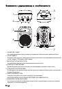
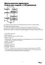
Controls and Features
1.POLE MOUNT SOCKET-This socket is designed to fit a standard speaker
pole mount or tripod speaker stand.
2.RIGGING POINTS-This series speaker has rigging points . These points are
to be used to fly or suspend the speaker in the air by some means . Be sure
to follow the flying outlines.
3.HIGH FREQUENCY TRANSDUCER - This unit is used to reproduce the high
frequency response..
4.WOOFER-The high-powered woofer is used to reproduce the
midrange and low frequencies.
5.TRANSPORT HANDLE-This series speakers come with built-in
heavy-duty transportation handle . Use this handle for secure
and easy transportation.
6.LUGGAGE-STYLE WHEELS-
.
allowing the unit to be easily
carried or pulled along on its luggage-style wheels
7.POLE MOUNT LOCKING BOLT- This pin is used to secure the
speaker in place when mounting the speaker in a pole mount
configuration . Always be sure to tighten down on the locking
bolt to prevent the speaker from shifting during use.
USB
MMC
SD
PLAY VOL+ VOL-
EQ
SD POWER
PAUSE NEXT PREV
PRT
USB
STOP
AC 230V 50Hz
POWER
GROUND
SMS15DP760LCD
HF:1.75 80W (44mm Ti dome drive)
"
"
LF:15 300W (75mm voice coil/60 oz magnet)
ACTIVE SOUND REINFORCEMENT SYSTEM
Internal Switch Mode Power Supply(SMPS)
Revolutionary Class-D Amplifier Technology
Nominal Impedance: 8 ohm
CLIP
MIC LEVEL
MIN
MAX
LINE LEVEL
MIN
MAX
VOLUME
MIN
MAX
-12
TREBLE
+12
BASS
-12
+12
POWER
LINE
OUTPUT
MIC
INPUT
R
L
LINE INPUT
SMS15DP760LCD REAR PANEL DESCRIPTION
1
2
3
4
5
6
7
9
10
11
12
13
15
16
8
14
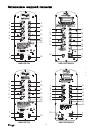
1. Mic XLR Input - Plug a mic directly into this port for public address
usage and let your voice be heard.
2. 1/4
”
MIC Input
–
Plug a mic directly into this port.
3. Balanced RCA Li ne Input
–
This connection is designed to accept
a balanced line input signal from a mixeror other line level device
with a balanced output jack. Use a balanced cable when the signal
cable length exceeds 15 feet, this will reduce excessive signal loss.
Be sure to connect only line level input devices such as mixers
and tape machines to this jack.
4. Balanced XLR Li ne Input
–
This connection is designed to
accept a balanced line input signal from a mixer or other line level
device with a balanced output jack. Use a balanced cable when
the signal cable length exceeds 15 feet, this will reduce excessive
signal loss.5.1/4
”
Line Output Jack
–
This jack is used to send
the incoming line level signal from either of the Line Level Inputs
Jacks to other powered speaker.
3
8
6. XLR LINE Output
–
Using a XLR cable, use this port to daisy chain from your this speaker to other powered
speaker.
7.Main Power Inlet
–
This connector is used to supply main power to the unit via the included detachable power
cord.
8.Fuse Holder
–
This housing stores the 3.15 amp GMA protective fuse. Always replace with the exact same type
fuse, unless otherwise instructed,
9. Microphone input Volume
–
This knob is used to increase or decrease the volume output on your speaker.
10. Line level input volume
–
This knob is used to regulate the output signal of theline level source connected to
the Line Level Inputs.
11. output volume
–
This knob is used to regulate the output signal being sent to other powered speaker.
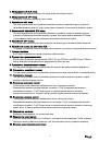
12. Treble control
–
This knob is used to regulate the amount treble applied to the output signal. The maximum
amount of treble gain is +12dB and the maximum amount of treble decrease is -12dB. Turning the knob in a
counter-clockwise direction will decrease the amount of treble applied to a channel signal, turning the knob in a
clockwise direction will increase the amount of treble applied to a channel signal.
13. Bass Control
–
This knob is used to regulate the amount bass applied to the
output signal. The maximum amount of bass gain is +12dB and the maximum amount of bass decrease is -12dB.
Turning the knob in a counter-clockwise direction will decrease the amount of bass applied to a channel signal,
turning the knob in a clockwise direction will increase the amount of bass applied to a channel signal.
14. Power indica tor led - LED lights up to indicate the speaker is on.
15. Clip Led - If this LED is lit it means your signal is clipping. To stop the signal from clipping lower the volume
to the point where the LED is blinking along with the bass beat.
16. AC VOLTOLTOLTAGEGE SELEELEELECTOTOR - This switch is used to change the operating voltage.
Operating voltage can be toggled between 115v or 230v/50~60Hz. Be sure the selector is set to the proper
voltage for your area before attempting to operate the unit. Always be sure main power is shut off before change
the position of the Voltage Selector Switch.
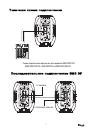
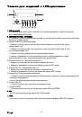
SMS15DP700 REAR PANEL DESCRIPTION
6. XLR LINE Output
–
Using a XLR cable, use this port to daisy chain from your this speaker to other
powered speaker.
7.Main Power Inlet
–
This connector is used to supply main power to the unit via the included detachable
power cord.
8.Fuse Holder
–
This housing stores the 3.15 amp GMA protective fuse. Always replace with the exact
same type fuse, unless otherwise instructed,
9. Microphone input Volume
–
This knob is used to increase or decrease the volume output on your
speaker.
10. Line level input volume
–
This knob is used to regulate the output signal of the line level source
connected to the Line Level Inputs.
11. output volume
–
This knob is used to regulate the output signal being sent to other powered speaker.
12. Treble control
–
This knob is used to regulate the amount treble applied to the output signal. The
maximum amount of treble gain is +12dB and the maximum amount of treble decrease is -12dB.
Turning the knob in a counter-clockwise direction will decrease the amount of treble applied to a
channel signal, turning the knob in a clockwise direction will increase the amount of treble applied to
a channel signal.
13. Bass Control
–
This knob is used to regulate the amount bass applied to the output signal. The
maximum amount of bass gain is +12dB and the maximum amount of bass decrease is -12dB. Turning
the knob in a counter-clockwise direction will decrease the amount of bass applied to a channel signal,
turning the knob in a clockwise direction will increase the amount of bass applied to a channel signal.
14. Power indica tor led - LED lights up to indicate the speaker is on.
15. Clip Led - If this LED is lit it means your signal is clipping. To stop the signal from clipping lower
the volume to the point where the LED is blinking along with the bass beat.
16. AC VOLTOLTOLTAGEGE SELEELEELECTOTOR - This switch is used to change the operating
voltage. Operating voltage can be toggled between 115v or 230v/50~60Hz. Be sure the selector is
set to the proper voltage for your area before attempting to operate the unit. Always be sure main
power is shut off before change the position of the Voltage Selector Switch.
SMS15DP700
CLIP
MIC LEVEL
MIN
MAX
LINE LEVEL
MIN
MAX
VOLUME
MIN
MAX
-12
TREBLE
+12
BASS
-12
+12
POWER
LINE
OUTPUT
MIC
INPUT
R
L
LINE INPUT
HF:1.75 80W (44mm Ti dome drive)
"
"
LF:15 300W (70mm voice coil/60 oz magnet)
ACTIVE SOUND REINFORCEMENT SYSTEM
Internal Switch Mode Power Supply(SMPS)
Revolutionary Class-D Amplifier Technology
Nominal Impedance: 8 ohm
AC 230V 50Hz
POWER
GROUND
1
2
3
4
5
6
7
9
10
11
12
13
15
16
8
14
1. Mic XLR Input - Plug a mic directly into
this port for public address usage and let
your voice be heard.
2. 1/4
”
MIC Input
–
Plug a mic directly in
to this port.
3. Balanced RCA Li ne Input
–
This connection
is designed to accept a balanced line input
signal from a mixer or other line level device
with a balanced output jack. Use a balanced
cable when the signal cable length exceeds
15 feet, this will reduce excessive signal loss.
Be sure to connect only line level input devices
such as mixers and tape machines to this jack.
4. Balanced XLR Li ne Input
–
This connection
is designed to accept a balanced line input signal
from a mixer or other line level device with
a balanced output jack. Use a balanced
cable when the signal cable length exceeds
15 feet, this will reduce excessive signal loss.
5.1/4
”
Line Output Jack
–
This jack is used
to send the incoming line level signal from
either of the Line Level Inputs Jacks to other
powered speaker.
SMS12DP700LCD REAR PANEL DESCRIPTION
6. XLR LINE Output
–
Using a XLR cable, use this port to daisy chain from your this speaker to other powered
speaker.
7.Main Power Inlet
–
This connector is used to supply main power to the unit via the included detachable power
cord.
8.Fuse Holder
–
This housing stores the 3.15 amp GMA protective fuse. Always replace with the exact same type
fuse, unless otherwise instructed,
9. Microphone input Volume
–
This knob is used to increase or decrease the volume output on your speaker.
10. Line level input volume
–
This knob is used to regulate the output signal of the line level source connected
to the Line Level Inputs.
11. output volume
–
This knob is used to regulate the output signal being sent to other powered speaker.
12. Treble control
–
This knob is used to regulate the amount treble applied to the output signal. The maximum
amount of treble gain is +12dB and the maximum amount of treble decrease is -12dB. Turning the knob in a
counter-clockwise direction will decrease the amount of treble applied to a channel signal, turning the knob in a
clockwise direction will increase the amount of treble applied to a channel signal.
13. Bass Control
–
This knob is used to regulate the amount bass applied to the output signal. The maximum
amount of bass gain is +12dB and the maximum amount of bass decrease is -12dB. Turning the knob in a
counter-clockwise direction will decrease the amount of bass applied to a channel signal, turning the knob in a
clockwise direction will increase the amount of bass applied to a channel signal.
14. Power indica tor led - LED lights up to indicate the speaker is on.
15. Clip Led - If this LED is lit it means your signal is clipping. To stop the signal from clipping lower the volume to
the point where the LED is blinking along with the bass beat.
16. AC VOLTOLTOLTAGEGE SELEELEELECTOTOR - This switch is used to change the operating voltage. Operating
voltage can be toggled between 115v or 230v/50~60Hz. Be sure the selector is set to the proper voltage for your
area before attempting to operate the unit. Always be sure main power is shut off before change the position
of the Voltage Selector Switch.
1
2
3
4
5
6
7
9
10
11
12
13
15
16
8
14
1. Mic XLR Input - Plug a mic directly into this port for public
address usage and let your voice be heard.
2. 1/4
”
MIC Input
–
Plug a mic directly into this port.
3. Balanced RCA Li ne Input
–
This connection is designed to
accept a balanced line input signal from a mixer or other line
level device with a balanced output jack. Use a balanced
cable when the signal cable length exceeds 15 feet, this will
reduce excessive signal loss. Be sure to connect only line level
input devices such as mixers and tape machines to this jack.
4. Balanced XLR Li ne Input
–
This connection is designed to
accept a balanced line input signal from a mixer or other line level
device with a balanced output jack. Use a balanced cable when
the signal cable length exceeds 15 feet, this will reduce excessive
signal loss.
5.1/4
”
Line Output Jack
–
This jack is used to send the incoming
line level signal from either of the Line Level Inputs Jacks to
other powered speaker.
SMS12DP700LCD
CLIP
MIC LEVEL
MIN
MAX
LINE LEVEL
MIN
MAX
VOLUME
MIN
MAX
-12
TREBLE
+12
BASS
-12
+12
POWER
LINE
OUTPUT
MIC
INPUT
R
L
LINE
INPUT
HF:1.35 80W (34mm Ti dome drive)
"
"
LF:12 300W (60mm voice coil/50 oz magnet)
ACTIVE SOUND REINFORCEMENT SYSTEM Internal Switch Mode Power Supply(SMPS)
Revolutionary Class-D Amplifier Technology
Nominal Impedance: 8 ohm
AC 230V 50Hz
POWER
GROUND
USB
MMC
SD
PLAY VOL+ VOL-
EQ
SD POWER
PAUSE NEXT PREV
PRT
USB
STOP
5
6
SMS12DP700
CLIP
MIC LEVEL
MIN
MAX
LINE LEVEL
MIN
MAX
VOLUME
MIN
MAX
-12
TREBLE
+12
BASS
-12
+12
POWER
LINE
OUTPUT
MIC
INPUT
R
L
LINE INPUT
HF:1.35 80W (34mm Ti dome drive)
"
"
LF:12 300W (60mm voice coil/50 oz magnet)
ACTIVE SOUND REINFORCEMENT SYSTEM
Internal Switch Mode Power Supply(SMPS)
Revolutionary Class-D Amplifier Technology
Nominal Impedance: 8 ohm
AC 230V 50Hz
POWER
GROUND
1
2
3
4
2
5
5
5
6
6
7
Controls and Features
1.POLE MOUNT SOCKET-This socket is designed to fit a standard speaker
pole mount or tripod speaker stand.
2.RIGGING POINTS-This series speaker has rigging points . These points are
to be used to fly or suspend the speaker in the air by some means . Be sure
to follow the flying outlines.
3.HIGH FREQUENCY TRANSDUCER - This unit is used to reproduce the high
frequency response..
4.WOOFER-The high-powered woofer is used to reproduce the
midrange and low frequencies.
5.TRANSPORT HANDLE-This series speakers come with built-in
heavy-duty transportation handle . Use this handle for secure
and easy transportation.
6.LUGGAGE-STYLE WHEELS-
.
allowing the unit to be easily
carried or pulled along on its luggage-style wheels
7.POLE MOUNT LOCKING BOLT- This pin is used to secure the
speaker in place when mounting the speaker in a pole mount
configuration . Always be sure to tighten down on the locking
bolt to prevent the speaker from shifting during use.
USB
MMC
SD
PLAY VOL+ VOL-
EQ
SD POWER
PAUSE NEXT PREV
PRT
USB
STOP
AC 230V 50Hz
POWER
GROUND
SMS15DP760LCD
HF:1.75 80W (44mm Ti dome drive)
"
"
LF:15 300W (75mm voice coil/60 oz magnet)
ACTIVE SOUND REINFORCEMENT SYSTEM
Internal Switch Mode Power Supply(SMPS)
Revolutionary Class-D Amplifier Technology
Nominal Impedance: 8 ohm
CLIP
MIC LEVEL
MIN
MAX
LINE LEVEL
MIN
MAX
VOLUME
MIN
MAX
-12
TREBLE
+12
BASS
-12
+12
POWER
LINE
OUTPUT
MIC
INPUT
R
L
LINE INPUT
SMS15DP760LCD REAR PANEL DESCRIPTION
1
2
3
4
5
6
7
9
10
11
12
13
15
16
8
14
1. Mic XLR Input - Plug a mic directly into this port for public address
usage and let your voice be heard.
2. 1/4
”
MIC Input
–
Plug a mic directly into this port.
3. Balanced RCA Li ne Input
–
This connection is designed to accept
a balanced line input signal from a mixeror other line level device
with a balanced output jack. Use a balanced cable when the signal
cable length exceeds 15 feet, this will reduce excessive signal loss.
Be sure to connect only line level input devices such as mixers
and tape machines to this jack.
4. Balanced XLR Li ne Input
–
This connection is designed to
accept a balanced line input signal from a mixer or other line level
device with a balanced output jack. Use a balanced cable when
the signal cable length exceeds 15 feet, this will reduce excessive
signal loss.5.1/4
”
Line Output Jack
–
This jack is used to send
the incoming line level signal from either of the Line Level Inputs
Jacks to other powered speaker.
3
8
6. XLR LINE Output
–
Using a XLR cable, use this port to daisy chain from your this speaker to other powered
speaker.
7.Main Power Inlet
–
This connector is used to supply main power to the unit via the included detachable power
cord.
8.Fuse Holder
–
This housing stores the 3.15 amp GMA protective fuse. Always replace with the exact same type
fuse, unless otherwise instructed,
9. Microphone input Volume
–
This knob is used to increase or decrease the volume output on your speaker.
10. Line level input volume
–
This knob is used to regulate the output signal of theline level source connected to
the Line Level Inputs.
11. output volume
–
This knob is used to regulate the output signal being sent to other powered speaker.
12. Treble control
–
This knob is used to regulate the amount treble applied to the output signal. The maximum
amount of treble gain is +12dB and the maximum amount of treble decrease is -12dB. Turning the knob in a
counter-clockwise direction will decrease the amount of treble applied to a channel signal, turning the knob in a
clockwise direction will increase the amount of treble applied to a channel signal.
13. Bass Control
–
This knob is used to regulate the amount bass applied to the
output signal. The maximum amount of bass gain is +12dB and the maximum amount of bass decrease is -12dB.
Turning the knob in a counter-clockwise direction will decrease the amount of bass applied to a channel signal,
turning the knob in a clockwise direction will increase the amount of bass applied to a channel signal.
14. Power indica tor led - LED lights up to indicate the speaker is on.
15. Clip Led - If this LED is lit it means your signal is clipping. To stop the signal from clipping lower the volume
to the point where the LED is blinking along with the bass beat.
16. AC VOLTOLTOLTAGEGE SELEELEELECTOTOR - This switch is used to change the operating voltage.
Operating voltage can be toggled between 115v or 230v/50~60Hz. Be sure the selector is set to the proper
voltage for your area before attempting to operate the unit. Always be sure main power is shut off before change
the position of the Voltage Selector Switch.
SMS12DP700
SMS15DP760
SMS12DP700LCD
SMS15DP760LCD