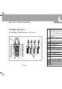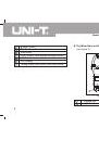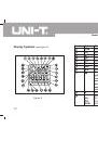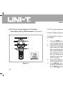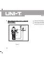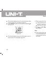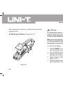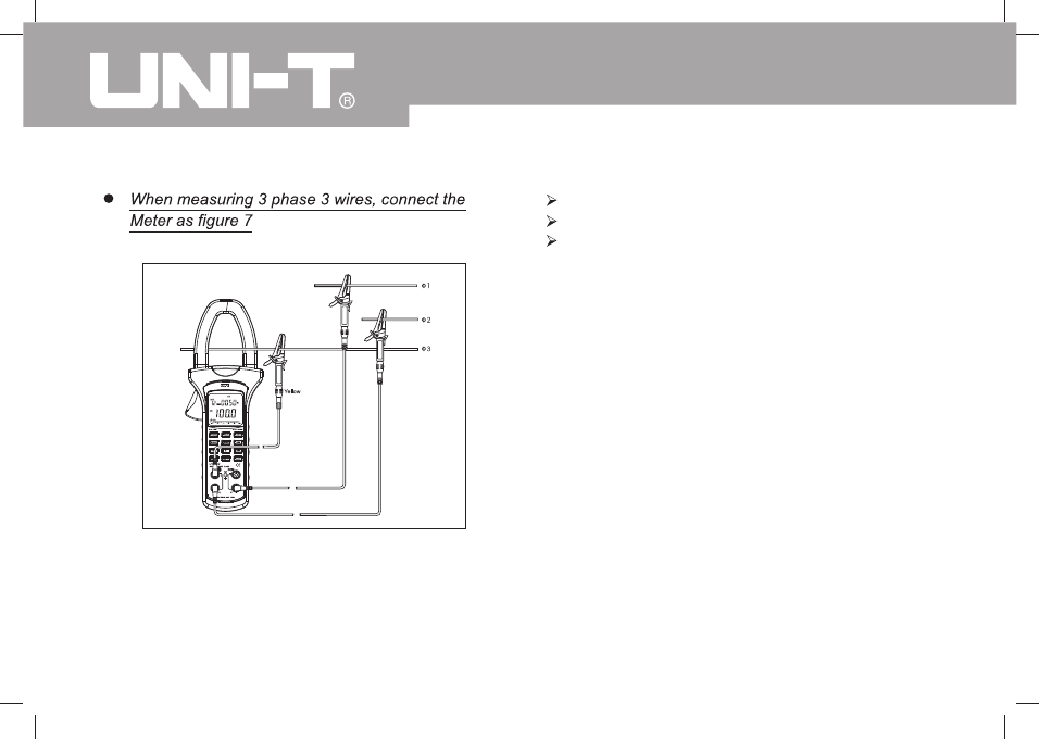
Figure 7
Model UT232: OPERATING MANUAL
20
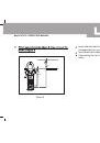
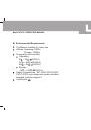
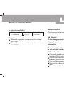
Insert red test leads to
V1
input terminal.
Insert blue test leads to
V2
input terminal
Insert yellow test leads to
V3
input terminal and
connect it to every live wire of the 3 phase.
Red
Blue
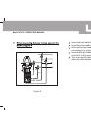
Figure 7
Model UT232: OPERATING MANUAL
20
Insert red test leads to
V1
input terminal.
Insert blue test leads to
V2
input terminal
Insert yellow test leads to
V3
input terminal and
connect it to every live wire of the 3 phase.
Red
Blue