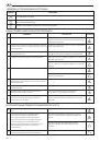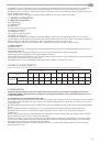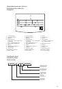
3.4. Setting/Adjusting LocalTime
To adjust the local time, the fi rst time the water heater is switched on it will automatically prompt you to
set the current time; on subsequent occasions you will need to press and hold the “Set” knob for 3 sec-
onds. Adjust the current hour setting by turning the “Set” knob, and then confi rm the value by pressing
the knob. Repeat the procedure to set the minute value.
4.
MAINTENANCE AND REPAIR WORKS
Attention! Do not try to repair the appliance by yourself. All maintenance and repair works should be carried
out by a qualifi ed technician in conformity with the safety norms and with any provisions set forth in this
manual.
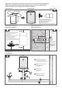
4.1. Water Drain
If there is a possibility that the ambient temperature drops below 0°C in the room where the appliance is installed, drain
water from the water heater.
4.1.1.
Disconnect the appliance from the electrical supply.
4.1.2.
Make sure that the water in the appliance is of safe temperature.
4.1.3.
Turn off the tap of cold water supply to the water heater.
4.1.4.
Turn on the hot water tap on mixer for pressure relief inside the tank.
4.1.5.
Turn on theT-connector stop valve installed at hot water outlet (marked with red ring) for air access into the tank. If
it is absent, remove the connections at the water heater outlet.
4.1.6.
Connect drain hose directed into the sewer to the T-connector stop valve installed at the cold water inlet of the
water heater (marked with the blue ring) and open it. If there is no T-connector, connect the hose to water heater inlet.
4.1.7.
After draining, make sure there is no water inside the water heater.
Freezing of water Inside the water heater leads to Irreversible changes and defects.
It Invalidates all warranty liability on the part of the manufacturer.
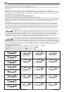
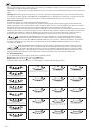
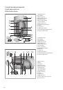
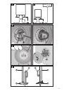
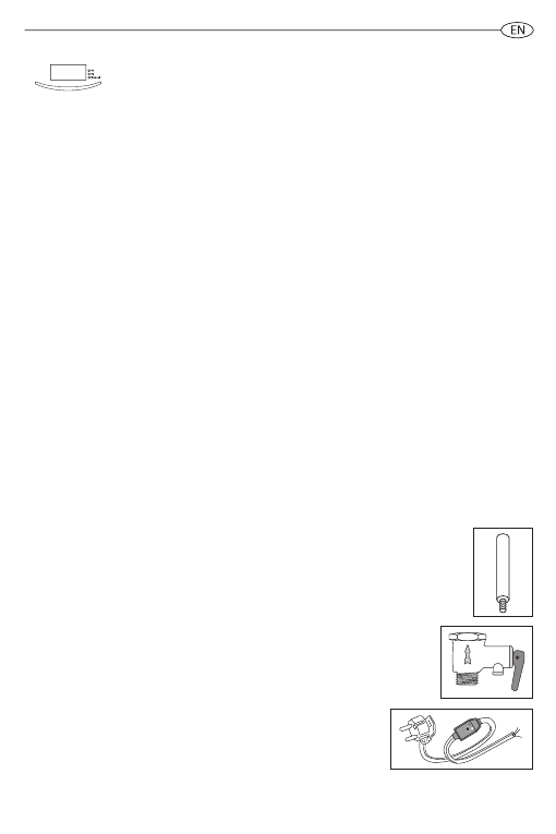
4.2. Replacing Internal parts
Disconnect the water heater from the electricity supply. Remove the appliance cover.
To replace the electronic thermostat (Ref.
T
) disconnect the power supply cable (Ref.
C
) and the display board wires (Ref.
Y
).
Next remove it from its slot.
To replace the display board (Ref.
W
), disconnect the wires (Ref.
Y
) and loosen the screws.
To replace the temperature sensor (Ref.
K
) disconnect the wires (Ref.
F
) from the main board and remove it from its slot .
To replace the display board (Ref.
W
), disconnect the wires (Ref.
Y
) and loosen the screws. To replace the main board (Ref.
Z
), disconnect the cables and wires (Ref.
C, Y, F
and
P
) and loosen the screws.
During reassembly, please, make sure that all components are put back In their original positions.
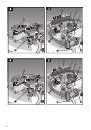
Prior to work, the water heater must fi rst be emptied. For models with an autoclave fl ange, remove the nut (
D
in Fig. 3)
and remove the bracket fi xing thefl angein place (
S
in Fig. 3), then press the fl ange (
F
in Fig. 3) inwardsand remove it with a
semicircular movement.
For models with a fl ange on the 5 bolts, loosen the 5 nuts (
C
in Fig. 4)and remove the fl ange (
F
in Fig. 4).
The heating element and anode are attached to the fl ange. During reassembly, make sure that the heating element, fl ange
gasket and the thermostat are put back in their original positions. We recommend the fl ange gasket is replaced every time
it is removed.
Prior to any repair or maintenance procedure, disconnect the unit from power source.
Use original spare parts of the manufacturer only.
4.3. Periodical maintenance
4.3.1. Magnesium anode
The magnesium anode rod is an integral part of the protection system of water tank against corrosion.
Ifs necessary to check the condition of the magnesium anode rod ANNUALLY.
Incase of severe wear, the magnesium anode rod must be replaced.
The warranty for water tank with the worn agnesium anode rod (residual volume is less than 30%) is not valid.
The magnesium anode rod should be replaced at least once in 24 months (except for the water heater with the
internal tank made of stainless steel).
The magnesium anode rod Is a consumable Item that cannot be replaced under warranty.
4.3.2. Safety valve
The safety valve (pressure safety device) must be inspected regularly to check that it is not
blocked or damaged. Replace the valve or remove limescale deposits if necessary. If the safety
valve is equipped with a lever, regular valve correct operation check procedure can be performed
with its help.
The drainage pipe of the safety valve may generate water droplets. It is not a defect; it is due to
relief work function of the valve - pressure relief that occurs when water is heated in enclosed
space of the inner tank.
4.3.3. RCD (Residual Current Device)
If the appliance comes with a residual current device (RCD) located on the power
cord, and then after the tank of the water heater is fi lled with water and the system is
checked for leaks, put in the electrical plug of the water heater and do the following:
- Press «RESET» knob on the RCD body, LED will be lit, indicating electricity supply.
- Then press «TEST» knob, power will be off , as well as LED.
- Press «RESET» knob again. If the power LED lit up, it means that the appliance is safe to use.
- If you press the «RESET» knob, but LED does not light up, contact the Technical Assistance Centre for advice by a qualifi ed
technician.
35