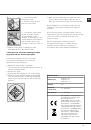
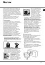
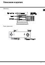
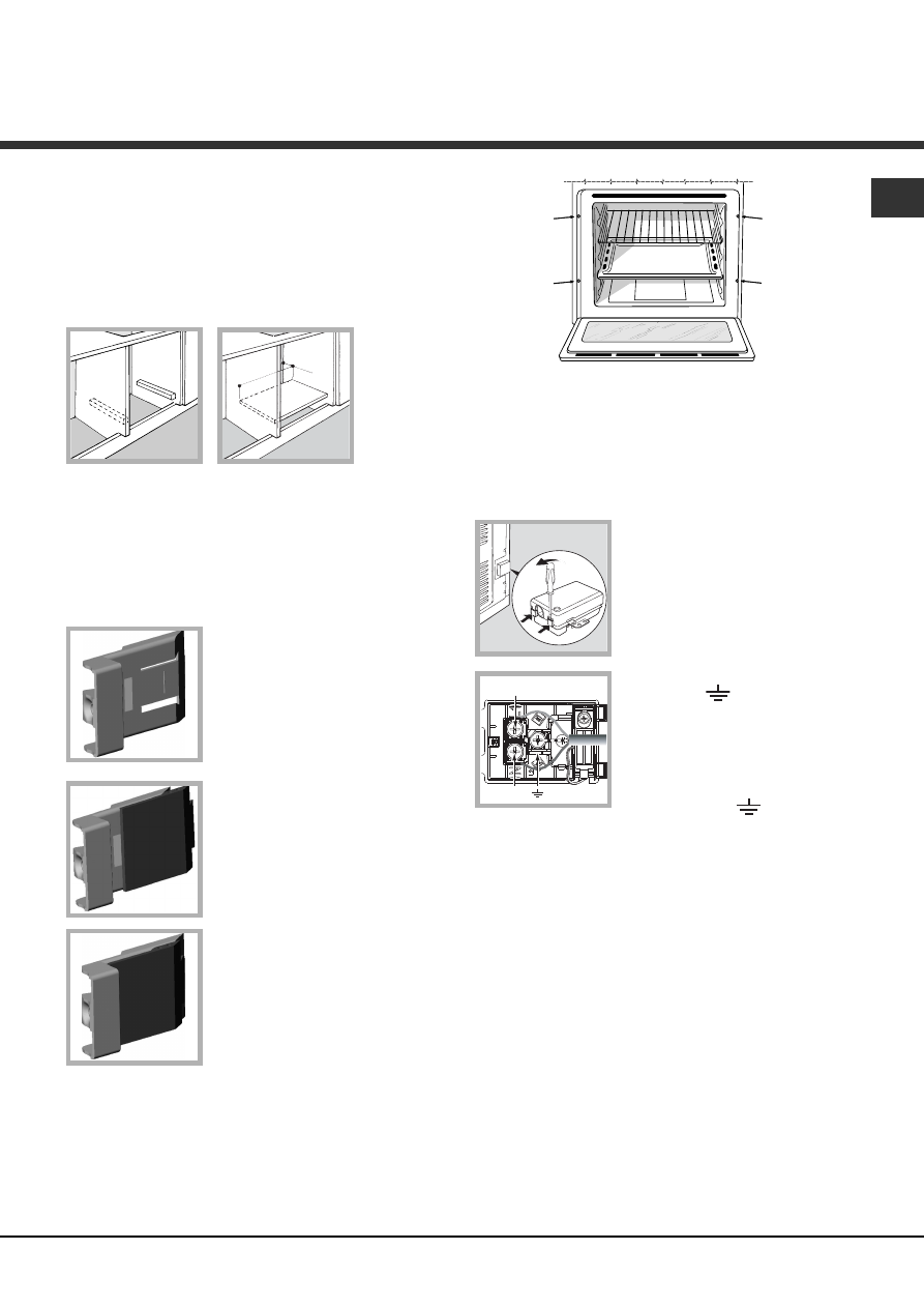
Инструкция для ARISTON Deco 7OFHR G

(скачивание инструкции бесплатно)
Формат файла: PDF
Доступность: Бесплатно как и все руководства на сайте. Без регистрации и SMS.
Дополнительно: Чтение инструкции онлайн
background image

GB

3

Ventilation

To ensure adequate ventilation, the back panel of
the cabinet must be removed. It is advisable to
install the oven so that it rests on two strips of wood,
or on a completely flat surface with an opening of at
least 45 x 560 mm (

see diagrams

).

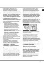
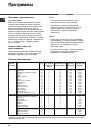
Centring and fastening

Position the 4 tabs on the side of the oven according
to the 4 holes on the outer frame. Adjust the tabs
according to the thickness of the cabinet side panel,
as shown below:

20 mm thick: take off the
removable part of the tab (

see

diagram

).

18 mm thick: use the first
groove, which has already
been set in the factory (

see

diagram

).

16 mm thick: use the second
groove (

see diagram

).

Secure the appliance to the cabinet by opening the
oven door and fastening 4 screws into the 4 holes of
the outer frame.

!

 All parts ensuring the safe operation of the

appliance must not be removable without the aid of
a tool.

Electrical connections

!

 Ovens equipped with a three-pole power supply

cable are designed to operate with alternating
current at the voltage and frequency indicated on
the data plate located on the appliance (

see below

).

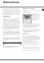
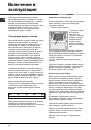
Fitting the power supply cable

1. Open the terminal board by
inserting a screwdriver into the
side tabs of the cover. Use
the screwdriver as a lever by
pushing it down to open the
cover (

see diagram

).

2. Install the power supply cable
by loosening the cable clamp
screw and the three wire contact
screws L-N-

. Connect the

wires to the corresponding
terminals: the Blue wire to the
terminal marked (N), the Brown
wire to the terminal marked (L)
and the Yellow/Green wire to the
terminal marked 

 (

see

diagram

).

3. Secure the cable by fastening the clamp screw.
4. Close the cover of the terminal board.

Connecting the supply cable to the mains

Install a standardised plug corresponding to the
load indicated on the data plate (

see adjacent box

).

The appliance must be directly connected to the
mains using an omnipolar circuit-breaker with a
minimum contact opening of 3 mm installed between
the appliance and the mains. The circuit-breaker must
be suitable for the charge indicated and must comply
with current electrical regulations (the earthing wire
must not be interrupted by the circuit-breaker). The
supply cable must not come into contact with
surfaces with temperatures higher than 50°C.

!

 The installer must ensure that the correct electrical

connection has been made and that it is compliant
with safety regulations.

560 mm.

45 m

m.

N

L

1
2
3
4
5
6
7
8
9
10
11
12
13
14
15
16
17
18
19
20
21
22
23
24
Оглавление инструкции
  • Страница 1 из 25
    Operating Instructions OVEN Contents GB Installation, 2-5 GB English, 1 RS Русский, 12 Positioning Electrical connection Gas connection Data plate Description of the appliance, 6 Overall view Control panel Start-up and use, 7-8 Starting the oven How to use the timer Burner and nozzle specifications
  • Страница 2 из 25
    Installation ! Before operating your new appliance please read this instruction manual carefully. It contains important information for safe use, installation and care of the appliance. The system can also provide the air needed for combustion indirectly, i.e. from adjacent rooms fitted with air
  • Страница 3 из 25
    Ventilation GB To ensure adequate ventilation, the back panel of the cabinet must be removed. It is advisable to install the oven so that it rests on two strips of wood, or on a completely flat surface with an opening of at least 45 x 560 mm (see diagrams). 560 mm . 45 m m. Electrical connections !
  • Страница 4 из 25
    GB Before connecting to the power supply, make sure that: NO OK • the appliance is earthed and the plug is compliant with the law. • the socket can withstand the maximum power of the appliance, which is indicated on the data plate (see below). • the voltage is in the range between the values
  • Страница 5 из 25
    3. Unscrew the burner fastening screws. 4. Remove screw “V” and then the oven burner. V 5. Make sure the burner does not switch off when you turn the knob from Max to Min quickly, or when you open and close the oven door quickly. GB ! If the appliance is connected to liquid gas, the regulation
  • Страница 6 из 25
    Description of the appliance GB Overall view GUIDES for the sliding racks Control panel position 5 position 4 position 3 position 2 position 1 GRILL DRIPPING PAN Control panel GRILL indicator light TIMER knob 0 0 1 Min Max 150 220 180 OVEN/GRILL knob 6 OVEN LIGHT button
  • Страница 7 из 25
    Start-up and use ! The first time you use your appliance, heat the empty oven with its door closed at its maximum temperature for at least half an hour. Ensure that the room is well ventilated before switching the oven off and opening the oven door. The appliance may produce a slightly unpleasant
  • Страница 8 из 25
    GB Cooling ventilation Oven light In order to cool down the external temperature of the oven, some models are fitted with a cooling fan that blows air out between the control panel and the oven door. ! Once the cooking has been completed, the cooling fan remains on until the oven has cooled down
  • Страница 9 из 25
    Cooking modes Cooking modes GRILL GRILL mode The top heating element comes on. The extremely high and direct temperature of the grill makes it possible to brown the surface of meats and roasts while locking in the juices to keep them tender. The grill is also highly recommended for dishes that
  • Страница 10 из 25
    Precautions and tips GB ! This appliance has been designed and manufactured in compliance with international safety standards. The following warnings are provided for safety reasons and must be read carefully. General safety • This is a class 3 built-in appliance. • Gas appliances require regular
  • Страница 11 из 25
    Maintenance and care Switching the appliance off Disconnect your appliance from the electricity supply before carrying out any work on it. F Cleaning the appliance ! Never use steam cleaners or pressure cleaners on the appliance. • The stainless-steel or enamel-coated external parts as well as the
  • Страница 12 из 25
    Руководство по эксплуатации ДУХОВОЙ ШКАФ Содержание RS Монтаж, 13-16 GB English, 1 RS Русский,12 Расположение Электрическое подсоединение Подсоединение к газопроводу Паспортная табличка Описание изделия, 17 Общий вид Панель управления Включение и эксплуатация, 18-19 Эксплуатация духового шкафа
  • Страница 13 из 25
    Монтаж ! Важно сохранить данное руководство для его последующих консультаций. В случае продажи, передачи изделия или при переезде на новое место жительства необходимо проверить, чтобы руководство оставалось вместе с изделием, для того чтобы его новый владелец мог ознакомиться с правилами
  • Страница 14 из 25
    RS ! После встраивания изделия в кухонный элемент должна быть исключена возможность касания к электрическими частями. Расход электроэнергии, указанный на паспортной табличке изделия, был замерен для данного типа монтажа. Вентиляция Для обеспечения надлежащей вентиляции необходимо снять заднюю
  • Страница 15 из 25
    В случае прямого подключения к сети электропитания между изделием и сетью необходимо установить многополюсный выключатель с минимальным расстоянием между контактами 3 мм, расчитанный на данную нагрузку и соответствующий действующим нормативам (выключатель не должен размыкать провод заземления).
  • Страница 16 из 25
    Проверка уплотнения RS ! По завершении подсоединения проверьте прочность уплотнения всех патрубков при помощи мыльного раствора, но никогда не пламенем. 4. поверните винт регуляции, расположенный снаружи стержня термостата, вплоть до получения стабильного малого пламени (пламя видно через отверстия
  • Страница 17 из 25
    Описание изделия Общий вид RS Панель управления 17
  • Страница 18 из 25
    Включение и эксплуатация RS ! При первом включении духового шкафа рекомендуем прокалить его примерно в течение часа при максимальной температуре с закрытой дверцей. Затем выключите духовой шкаф, откройте дверцу и проветрите помещение. Запах, который вы можете почувствовать, вызван испарением
  • Страница 19 из 25
    Охладительная вентиляция Для понижения температуры вокруг работающего духового шкафа некоторые модели оснащаются охладительным вентилятором. Этот вентилятор направляет струю воздуха между панелью управления и дверцей духового шкафа. ! По завершении приготовления вентилятор продолжает работать
  • Страница 20 из 25
    Программы RS Программы приготовления ГРИЛЬ Программа ГРИЛЬ Включается верхний нагревательный элемент. Значительная температура прямого действия гриля позволяет получить быстрое образование корочки на поверхности продукта, которая препятствует выходу соков и сохраняет продукт нежным и сочным внутри.
  • Страница 21 из 25
    Предосторожности и рекомендации ! Изделие спроектировано и изготовлено в соответствии с международными нормативами по безопасности. Необходимо внимательно прочитать настоящие предупреждения, составленные в целях вашей безопасности. Общие требования к безопасности • Данное устройство является
  • Страница 22 из 25
    Техническое обслуживание и уход RS Отключение электропитания Перед началом какой-либо операции по обслуживанию или чистке отсоедините изделие от сети электропитания. F Чистка изделия ! Не используйте паровые чистящие агрегаты или агрегаты под высоким давлением для чистки изделия. • Наружные
  • Страница 23 из 25
    RS 23
  • Страница 24 из 25
    03/2012 - 195079900.04 XEROX FABRIANO RS 24
  • Страница 25 из 25