8
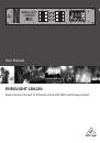
EUROLIGHT LD6230 User Manual
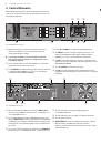
4. Connectors and Initial Operation
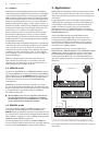
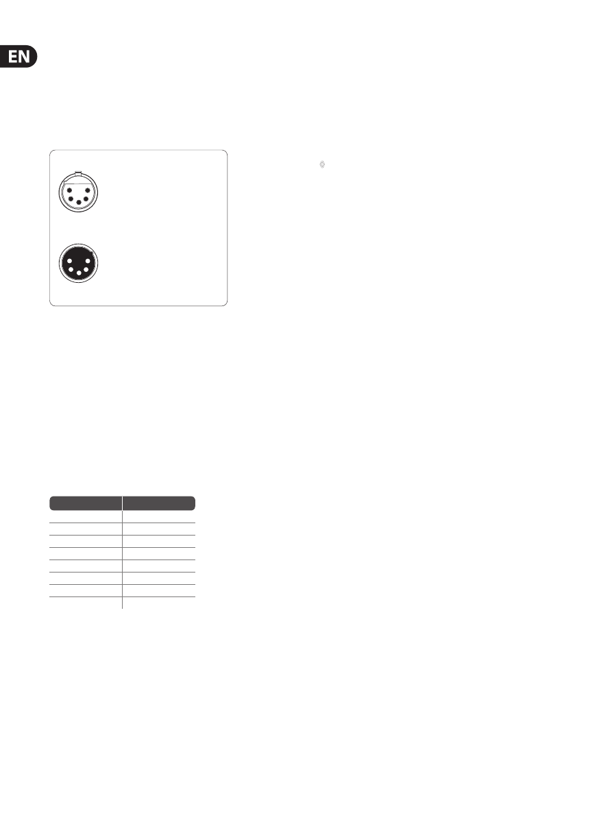
4.1 Digital DMX connector
The DMX512 IN and DMX512 OUT connectors are made in accordance
with the international DMX512 standard. 5-pole XLR connectors are used,
whereby controllers and DMX senders feature female connectors, while receiver
equipment such as dimmer packs feature male connectors.
1 = Signal common/shield
2 = Data 1 (-)
3 = Data 2 (+)
5-pin XLR connectors for DMX512 signals
Pins 4 (data 2 -) and 5 (data 2 +) are not connected (optional use)
Fig. 4.1: Pin assignment of a 5-pin XLR connector
You should stick to the pin assignment shown in above illustration even when
two reserve pins 4 and 5 are used for a second connection (a separate sender
and receiver unit).
Often, 3-pole XLR connectors are also used for transmitting digital
control signals, since these connectors simplify using the wiring already
at the user’s disposal and are also less expensive than 5-pole connectors.
However, these connectors are substandard and may not carry the
“DMX512” insignia.
4.2 Analog connector
An 8-pole DIN connector is used as the input connection for an analog control
signal (0-10 V).
PIN
CHANNEL
1
1
2
2
3
3
4
4
5
5
6
6
7
NC
8
GROUND
Tab. 4.1: Pin assignment of an 8-pin DIN connector
4.3 EEP (Eprom Check)
An eprom (Erasable Programmable Read Only Memory) is an electronic device
that contains programs or data needed to operate a piece of equipment.
Once you “burn” data onto an eprom, it can’t get lost, even when you power
down your equipment.
During the power-up procedure of your LD6230, the eprom is checked, that is,
the LD6230 looks for false values (plausibility control). If irregularities occur
during the eprom initialisation, factory default values are loaded.
◊
To erase the contents of the eprom and load factory defaults, keep both
middle keys (UP and DOWN) pressed while powering up your LD6230.
4.4 Phase allocation
The LEDs L1, L2 and L3 (
(6)
) indicate phase condition. L1 refers to channels 1
and 2, L2 refers to channels 3 and 4, and L3 refers to channels 5 and 6. The LEDs
show if correct voltage is applied to your EUROLIGHT LD6230. If the voltage is
not correct (i.e. too high or too low), the corresponding LED(s) begin to blink.
Since the dimmer’s circuitry is powered by all three phases, the dimmer remains
functioning even if two out of three phases malfunction. However, to guarantee
trouble-free operation, always attempt to correct phase problems as soon as they
are discovered.