7
ULTRACURVE PRO DEQ2496 User Manual
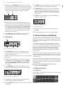
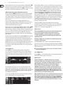
On pages 1 and 2 of the DEQ menu you can adjust the necessary settings to
determine the threshold and the way of sound processing. Additionally, you will
find a graphic representation of the control curve with regard to THRESHOLD,
GAIN and RATIO. In the center of the display, the LEVEL meter (left) indicates the
filtered DEQ input level (control signal), while the GAIN meter (right) shows how
much boost/cut is applied to the signal.
Page 3 includes a frequency diagram showing the filter curves with regard to
frequency and threshold. The current DEQ input level can be seen from the LEVEL
meter on the right.
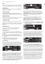
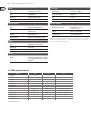
Fig. 3.4: DEQ menu (page 1)
The make-up gain parameter
M-GAIN
on page 1 allows you to set the amount
of boost/cut for the filter with the upper data wheel. The setting range is from
-15 to +15 dB.
THRESHOLD
(large data wheel) defines the threshold as of which
the filter function is activated. If the filter has been set to attenuate the signal
(M-GAIN < 0), then the desired frequency range (see page 3) will be lowered
in level as soon as it exceeds the threshold. If boost is required (M-GAIN > 0),
the frequency range will be raised in level as soon as the signal drops below the
threshold. The
RATIO
parameter (lower data wheel) determines the amount
of boost/cut applied to the respective frequency range, if the signal exceeds or
drops below the threshold. The setting range is from 1:2 to 1:100.
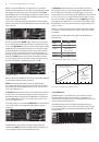
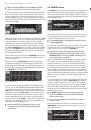
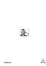
Fig. 3.5: DEQ menu (page 2)
On the second page of the DEQ menu (accessed by pressing the DEQ or PAGE key),
you can define two additional dynamics parameters.
ATTACK
(upper data wheel) determines how fast the dynamic EQ starts
processing when the signal exceeds or drops below the threshold. The ATTACK
times available range from 0 to 200 milliseconds. Press this control to select a
coarse or fine adjustment scale.
The
RELEASE
parameter (lower data wheel) lets you adjust the time needed by
the EQ to “release” the sound after the signal has exceeded or dropped below
threshold (depending on the GAIN setting). The RELEASE times available range
from 20 to 4,000 milliseconds. Here, too, you can press the control to select a
coarse or fine adjustment scale.
It is on this page that you can also edit the
THRESHOLD
value (large data wheel),
so as to be able to make some readjustments without having to change to
another page.
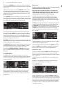
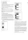
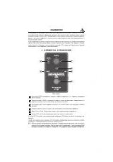
Fig. 3.6: DEQ menu (page 3)
As mentioned before, page 3 includes a frequency diagram and the gain
reduction meter.
MODE
(upper data wheel) defines the filter type, and you can
choose from high-shelving, low-shelving and band-pass filters.
The
FREQUENCY
parameter determines the center frequency of the filter
(large data wheel). In the case of low-shelving and high-shelving filters, this is
the cut-off frequency as of which the low or high frequencies are processed.
The entire frequency spectrum ranges from 20 to 20,000 Hz. Press the data wheel
to select a coarse (1/6 oct. per step) or fine adjustment scale (1/60 oct. per step).
If you selected “bandpass” under MODE, the parameter
BW(OCT)
appears in the
lower right part of the display. Here, you can use the lower data wheel to adjust
the bandwidth of your choice and thus determine the “width” of the filter curve
(1/10 oct. to 10 oct.).
The B key selects which of the dynamic EQs is displayed. Three EQs are available
for each stereo side. Keep the key pressed to reset the settings of the currently
selected DEQ.
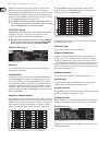
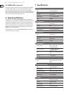
This table shows an example with extreme settings, thus illustrating how a
dynamic EQ works:
Settings
MODE
BP
FREQ
1.00 kHz
M-GAIN
+15 dB > continuous line
0 dB > broken line
-15 dB > dotted line
BW(OCT)
0.1
THRESHOLD
-40 dB
RATIO
1:100
Tab. 3.1: Bandpass with extreme settings (see also fig. 3.7)
0 dB
0 dB
-40 dB
Positive gain > gain boost
after dropping below threshold
-40 dB
Threshold
Negative gain >
gain reduction
after exceeding
threshold
Fig. 3.7: Filter curves with signal above/below the threshold
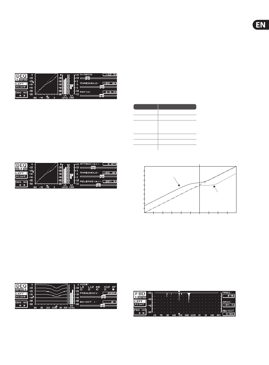
3.2.4 FBD menu
The DEQ2496 features a “Feedback Destroyer” function, which corresponds
largely to the PEQ menu as far as operation and choice of parameters are
concerned. However, the FBD menu has some additional functions and therefore
comprises three pages rather than just two.
The Feedback Destroyer allows you to apply heavy attenuation (no boost)
to specific frequency ranges, so as to remove certain frequencies that are liable
to cause feedback. With its extermely narrow-band filters it hardly affects the
overall sound at all.
Fig. 3.8: FBD menu (page 1)