8
ULTRACURVE PRO DEQ2496 User Manual
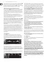
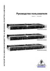
The first page shows a graphic representation of the filters. It is structured and
operated in the same way as the first page in the PEQ menu. Since this menu
can only be used to cut signals, the 0 dB line is located in the upper part of the
display. The differences here are the settings ranges for the GAIN and BW(OCT)
parameters. In order to achieve extremely narrow-band filters with high
attenuation factors, the bandwidth ranges from 1/10 to 1/60 oct. and the GAIN
from 0 to -60 dB.
◊
At least one filter must be activated on page 2 to be able to access the
first page of the FBD menu.
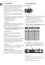
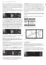
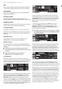
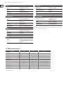
Fig. 3.9: FBD menu (page 2)
Page 2 provides a table showing the ten memory locations available.
If parametric EQs have been activated in the PEQ menu, these will be shown here
too, because the memory locations are intended for both FBD and PEQ settings.
◊
Any parametric EQs activated in the PEQ module cannot be edited in
the Feedback Destroyer menu (FBD)—and vice versa.
In general, you can select two types of feedback filters: SNGL mode (single shot)
and AUTO mode. To be able to identify feedback frequencies, the Feedback
Destroyer splits up the entire frequency spectrum (20 Hz to 20 kHz) into bands of
1/60 octave and measures their respective levels. The resulting values are then
referenced to the level of the complete signal. The difference between these
levels determines whether a filter is activated or not. As soon as a filter is set
to AUTO or SNGL mode, the unit automatically tracks feedback frequencies and
assigns the active filters to them.
AUTO mode
Microphones that are moved around during a performance (e.g. vocal mics)
often suffer from varying feedback frequencies as a result of the changing
positions on stage. This kind of feedback is best suppressed in AUTO mode.
A filter in AUTO mode automatically identifies the optimum parameter settings
for feedback suppression. If the feedback frequencies change, the AUTO filter
can track them and keep suppressing them. It always selects the respective
frequencies and a very narrow-band filter configuration to affect the wanted
signal as little as possible. When all filters are locked in to a specific frequency,
and a “new” feedback frequency occurs, then the filter with the “oldest” or
first feedback frequency detected is released and used for the new one. If new
feedback occurs very close to or even at an already identified frequency,
the parameters of the filter already in use will be adapted, for example by
widening its bandwidth or raising the amount of signal attenuation.
SNGL mode
Filters in SNGL mode (single shot) also searches feedbacks automatically.
If feedback is identified, the filter parameters are configured optimally for
feedback suppression. Contrary to filters in AUTO mode, filters in SNGL mode lock
in firmly to the identified frequency (LOCK FBD), however, their width and depth
are still being adapted to changes in the feedback frequencies. The bandwidth is
enlarged, if the feedback frequency shifts slightly, and the amount of attenuation
is raised if feedback persists. To prevent a feedback frequency from recurring,
the amount of attenuation is not reduced. Thus, SNGL mode is ideally suited to
suppress constant feedback frequencies, as they are typically produced by fixed
or permanently installed microphones.
Use the
LOCK FBD
function (B key in the left bottom part of the display) to lock
the frequency of the SNGL filter manually (SNGL
). This means that the filter can
only be modified in its bandwidth and amount of attenuation. With UNLOCK FBD
(B key) it can be unlocked again.
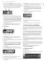
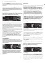
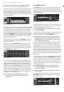
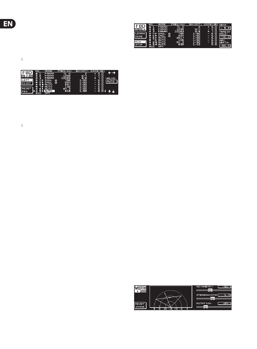
Fig. 3.10: FBD menu (page 3)
The third page provides three additional dynamics parameters for all FBD filters.
SENS
(upper data wheel) allows you to determine the point of onset for feedback
suppression (describes the difference between feedback signal and overall
level). When a signal reaches this difference, it gets reduced in level. The setting
range here is from -3.0 to -9.0 dB. Use
THRESHOLD
(large data wheel) to select
the threshold from which a certain frequency is considered to be feedback.
The
MAX. DEPTH
parameter below determines the maximum attenuation of a
filter (-18 to -60 dB) in 6 dB steps, and thus the GAIN setting range as displayed
on the first and second page (lower data wheel).
LEARN MODE
is activated with the A key. This function generates additional
short pulses and raises the overall gain to provoke feedback. Subsequently,
the feedback signals arrive at the input of the DEQ2496, are identified and
suppressed. LEARN MODE is ideal for use before a live event, for example to
automatically configure the SNGL filters (“tuning-in” of a P.A. system).
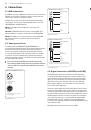
The following symbols inform you about the current status of the filters:
In this setting, an AUTO or SNGL filter is “on duty” (RUN) to react to the
incoming signal and effect the necessary settings.
This symbol refers to an AUTO or SNGL filter (SNGL filter in LOCK mode),
which is currently suppressing an identified feedback frequency.
This symbol indicates that the AUTO and SNGL filters are in STOP mode.
The settings already made remain active. However, “new” feedback
frequencies are not eliminated.
This symbol refers to the filter assigned to the last feedback
frequency identified.
The selection and editing of parameters is largely the same as in the
PEQ menu, one exception being the B key: With a long key press you can
reset all filters (menu page 2) or just the AUTO filters (menu page 3).
3.3 WIDTH menu
The WIDTH function gives you a stereo imager for processing stereo signals and is
active in stereo LINK mode only.
A signal whose stereo basis has been enlarged sounds much more interesting,
because you can hear more pronounced differences between the two stereo
sides. If used moderately, a stereo imager can clearly enhance the overall
impression of your music.
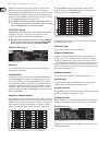
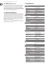
On both pages of the WIDTH menu, the parameters to be edited appear on
the right-hand side. On the left you’ll find the RESET IMAGE-function (B key),
which allows you to undo the previously made entries by means of a long key
press. In the center of the display, a diagram shows both the stereo width of
the signal (triangle) and the mono signal (line).
Fig. 3.11: WIDTH menu (page 1)