
34.21
•
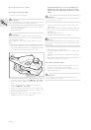
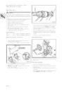
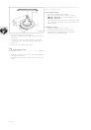
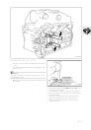
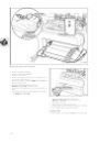
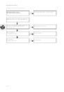
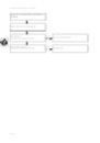
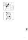
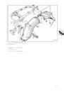
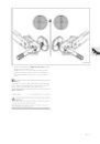
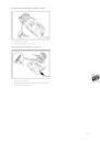
Install a new cover (1).
e
Caution:
When pushing on, make sur that all cables are cor-
rectly located in their guides.
Scrap the old cover.
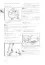
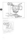
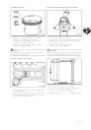
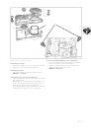
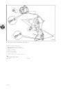
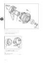
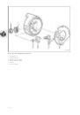
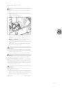
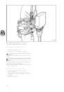
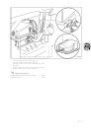
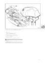
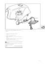
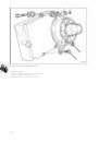
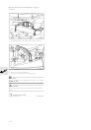
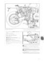
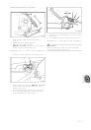
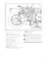
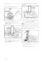
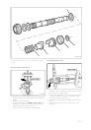
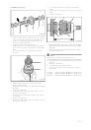
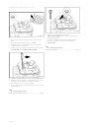
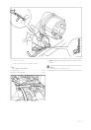
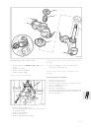
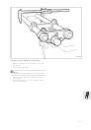
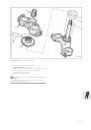
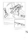
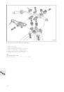
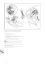
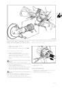
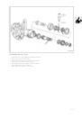
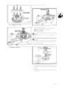
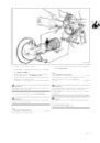
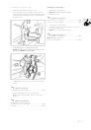
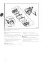
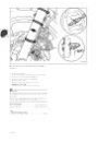
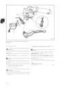
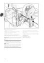
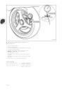
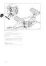
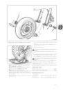
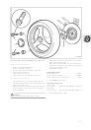
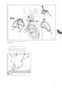
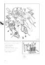
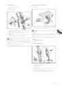
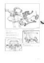
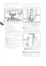
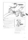
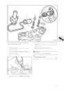
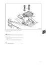
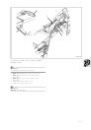
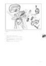
[ABS II] Removing relay base
e
Caution:
Switch off the ignition and disconnect and insulate
the earth (ground) lead.
•
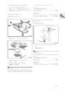
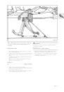
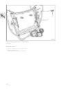
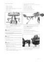
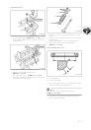
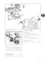
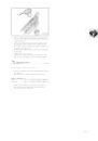
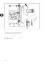
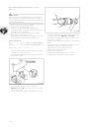
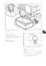
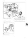
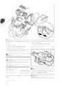
Remove cover (1) from ABS control unit, press in
the catch with a screwdriver and pull the cover
off upwards.
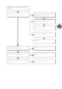
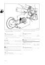
•
Scrap the cover.
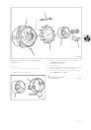
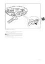
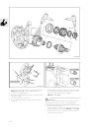
•
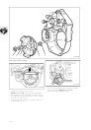
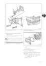
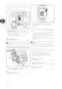
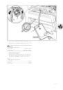
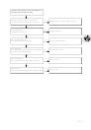
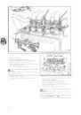
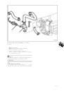
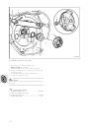
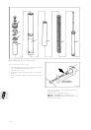
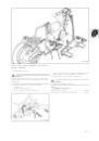
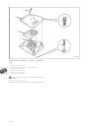
Disconnect leads (2) and scrap the nuts.
e
Caution:
Do not tilt the cables or the insultation may be dam-
aged.
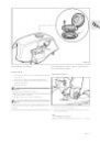
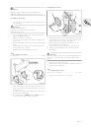
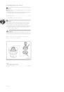
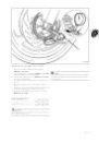
•
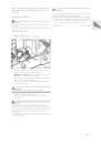
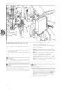
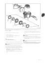
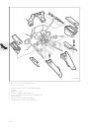
Pull off the 2-pin plug.
•
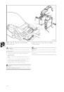
Take out relay base (4).
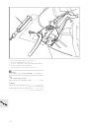
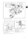
•
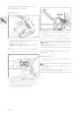
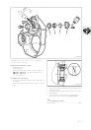
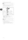
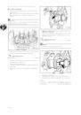
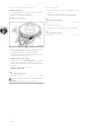
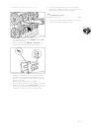
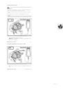
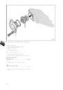
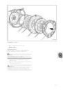
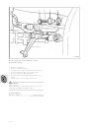
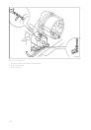
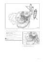
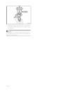
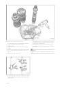
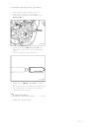
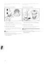
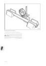
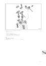
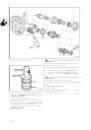
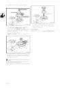
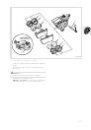
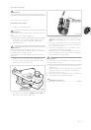
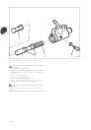
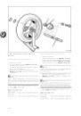
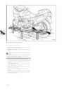
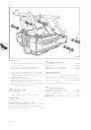
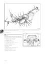
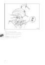
Take out screws on relay base with a Torx T20
screwdriver.
•
Remove the ABS relay
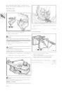
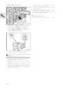
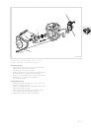
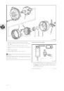
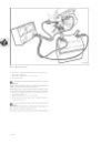
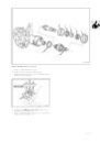
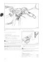
•
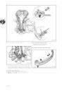
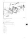
Press the contact lock out of the relay base.
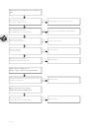
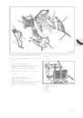
•
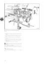
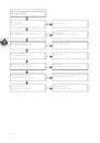
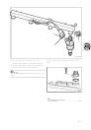
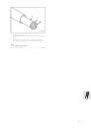
Using the special tool, Article No. 50000-017-
507 from the Grote und Hartmann company,
insert the plug from the relay side.
e
Caution:
The contact has a double locking action.
When pulling the plug out of the relay base, do not
exert too much tension on the cable.
If the cable breaks off, the complete ABS will have
to be renewed.
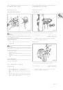
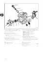
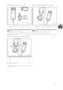
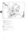
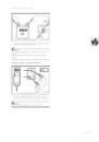
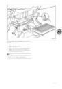
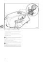
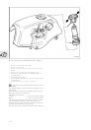
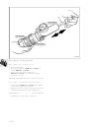
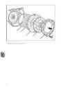
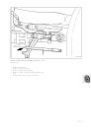
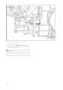
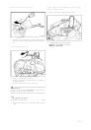
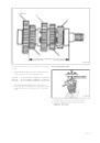
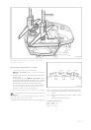
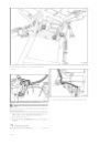
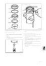
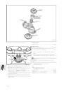
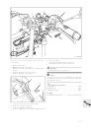
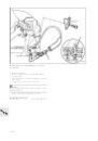
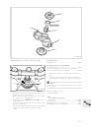
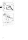
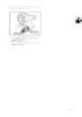
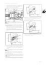
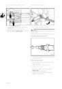
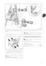
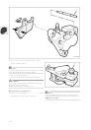
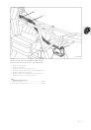
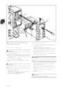
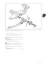
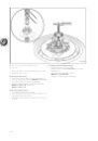
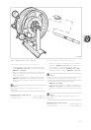
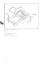
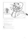
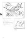
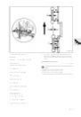
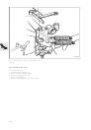
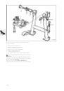
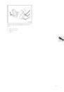
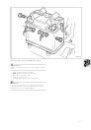
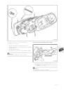
[ABS II] Installing relay base
•
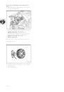
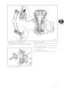
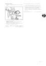
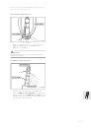
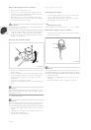
Ben up the contact lock for the plug.
•
Insert the contact into the relay base.
e
Caution:
The contact must be heard to engage, and must be
firmly seated.
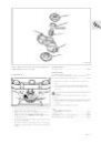
•
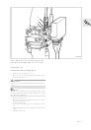
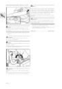
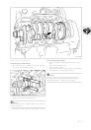
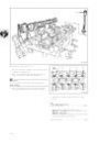
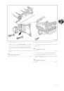
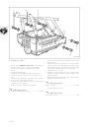
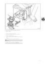
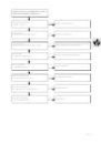
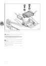
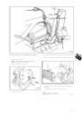
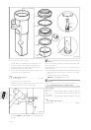
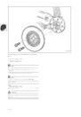
Insert ABS relay with FAG logo in the direction of
the retaining hook.
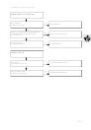
•
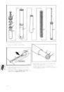
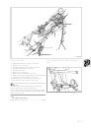
Insert one Torx screw into the ring cable shoe on
the red engine lead.
L
Note:
The crimp side must face toward the screw head.
e
Caution:
The same Torx screws must be used because of
their self-locking acition. When inserting, make sure
that the thread already present in the sheet metal is
entered again.
Failing this, the screws could come loose when ex
posed to vibration.
•
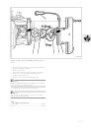
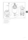
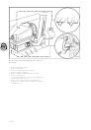
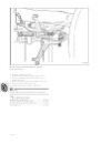
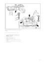
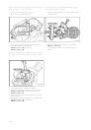
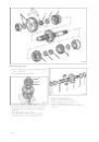
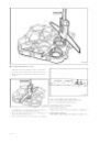
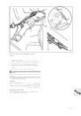
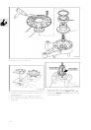
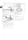
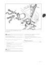
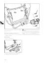
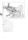
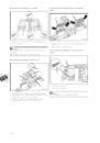
Place the ring cable shoe (with two leads) on the
hole in the insert on the rear of the relay base,
with the crimped side facing the relay base, and
screw on together with the red engine lead, us-
ing a Torx screw.
•
With the second Torx screw, attach the flat plug
to the relay.
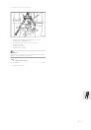
•
Press the contact lock into the relay base at the
side.
•
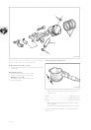
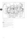
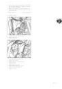
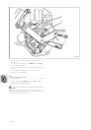
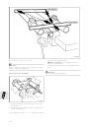
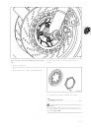
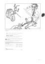
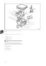
Push the relay base into the relay housing and at
the same time press both engine leads into the
left cable guide on the relay housing (red at bot-
tom, black at top).
•
Place the black engine lead on the left threaded
pin (M5) with the crimp facing to the rear.
e
Caution:
Do not tilt the cable, or the insulation may be dam-
aged.
•
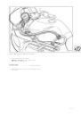
Attach the 2-pin plug in the correct position and
push on as far as it will go, at the same time
pressing the two leads into the centre (smaller)
cable guides.
•
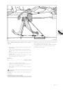
Place both plugs of the connecting lead/wiring
harness on to the threaded pins with the crimp
facing forwards.
•
Press both leads into the remaining unoccupied
cable guides.
•
Tighten the nuts.
e
Caution:
Always use new self-locking nuts.
•
Install a new cover (1).
e
Caution:
When sliding into position, make sure that all cables
are in the correct guides.
 1
1
 2
2
 3
3
 4
4
 5
5
 6
6
 7
7
 8
8
 9
9
 10
10
 11
11
 12
12
 13
13
 14
14
 15
15
 16
16
 17
17
 18
18
 19
19
 20
20
 21
21
 22
22
 23
23
 24
24
 25
25
 26
26
 27
27
 28
28
 29
29
 30
30
 31
31
 32
32
 33
33
 34
34
 35
35
 36
36
 37
37
 38
38
 39
39
 40
40
 41
41
 42
42
 43
43
 44
44
 45
45
 46
46
 47
47
 48
48
 49
49
 50
50
 51
51
 52
52
 53
53
 54
54
 55
55
 56
56
 57
57
 58
58
 59
59
 60
60
 61
61
 62
62
 63
63
 64
64
 65
65
 66
66
 67
67
 68
68
 69
69
 70
70
 71
71
 72
72
 73
73
 74
74
 75
75
 76
76
 77
77
 78
78
 79
79
 80
80
 81
81
 82
82
 83
83
 84
84
 85
85
 86
86
 87
87
 88
88
 89
89
 90
90
 91
91
 92
92
 93
93
 94
94
 95
95
 96
96
 97
97
 98
98
 99
99
 100
100
 101
101
 102
102
 103
103
 104
104
 105
105
 106
106
 107
107
 108
108
 109
109
 110
110
 111
111
 112
112
 113
113
 114
114
 115
115
 116
116
 117
117
 118
118
 119
119
 120
120
 121
121
 122
122
 123
123
 124
124
 125
125
 126
126
 127
127
 128
128
 129
129
 130
130
 131
131
 132
132
 133
133
 134
134
 135
135
 136
136
 137
137
 138
138
 139
139
 140
140
 141
141
 142
142
 143
143
 144
144
 145
145
 146
146
 147
147
 148
148
 149
149
 150
150
 151
151
 152
152
 153
153
 154
154
 155
155
 156
156
 157
157
 158
158
 159
159
 160
160
 161
161
 162
162
 163
163
 164
164
 165
165
 166
166
 167
167
 168
168
 169
169
 170
170
 171
171
 172
172
 173
173
 174
174
 175
175
 176
176
 177
177
 178
178
 179
179
 180
180
 181
181
 182
182
 183
183
 184
184
 185
185
 186
186
 187
187
 188
188
 189
189
 190
190
 191
191
 192
192
 193
193
 194
194
 195
195
 196
196
 197
197
 198
198
 199
199
 200
200
 201
201
 202
202
 203
203
 204
204
 205
205
 206
206
 207
207
 208
208
 209
209
 210
210
 211
211
 212
212
 213
213
 214
214
 215
215
 216
216
 217
217
 218
218
 219
219
 220
220
 221
221
 222
222
 223
223
 224
224
 225
225
 226
226
 227
227
 228
228
 229
229
 230
230
 231
231
 232
232
 233
233
 234
234
 235
235
 236
236
 237
237
 238
238
 239
239
 240
240
 241
241
 242
242
 243
243
 244
244
 245
245
 246
246
 247
247
 248
248
 249
249
 250
250
 251
251
 252
252
 253
253
 254
254
 255
255
 256
256
 257
257
 258
258
 259
259
 260
260
 261
261
 262
262
 263
263
 264
264
 265
265
 266
266
 267
267
 268
268
 269
269
 270
270
 271
271
 272
272
 273
273
 274
274
 275
275
 276
276
 277
277
 278
278
 279
279
 280
280
 281
281
 282
282
 283
283
 284
284
 285
285
 286
286
 287
287
 288
288
 289
289
 290
290
 291
291
 292
292
 293
293
 294
294
 295
295
 296
296
 297
297
 298
298
 299
299
 300
300
 301
301
 302
302
 303
303
 304
304
 305
305
 306
306
 307
307
 308
308
 309
309
 310
310
 311
311
 312
312
 313
313
 314
314
 315
315
 316
316
 317
317
 318
318
 319
319
 320
320
 321
321
 322
322
 323
323
 324
324
 325
325
 326
326
 327
327
 328
328
 329
329
 330
330
 331
331
 332
332
 333
333
 334
334
 335
335
 336
336
 337
337
 338
338
 339
339
 340
340
 341
341
 342
342
 343
343
 344
344
 345
345
 346
346
 347
347
 348
348
 349
349
 350
350
 351
351
 352
352
 353
353
 354
354
 355
355
 356
356
 357
357
 358
358
 359
359
 360
360
 361
361
 362
362
 363
363
 364
364