11
loss of power. To keep this to a minimum and to prevent
overheating and motor burn-out, ask advice from a
qualified electrician to determine the minimum wire size
of the extension lead. If the power cable is broken, repair
service is available at your nearest
FELISATTI
service
centre.
MOUNTING THE TOOL
NOTE:
We highly recommend that you bolt this mitre
saw securely to a work bench to gain the maximum stability
of your machine. Ensure that the machine is always fixed to
a bench whenever possible.
1. Locate and mark the four bolt holes on the bench.
2. Drill the bench with an Ø10 mm drill bit.
3. Bolt the mitre saw on to the bench with bolts,
washers and nuts. Note that these fasteners are not
supplied with the machine.
OPERATING THE TOOL
WARNING!
Never connect the plug to the power
source outlet until all installations and adjustments are
completed and you have read and understood the safety
and operational instructions.
Basic Pullover Mitre Saw Operations
1. Always use the clamp to hold the work piece firmly.
Two holes are provided for the clamp.
2. Always position the work piece against the fence.
Any piece that is bowed or warped and cannot be held flat
on the table or against fence may trap the blade and should
not be used.
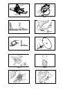
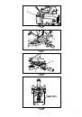
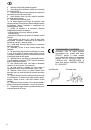
Body and Hand Position (Fig. 33)
Never place hands near cutting area. Keep hands
outside the “No Hands Zone” which includes entire table
and is labeled by “No Hands” symbols.
WARNING!
To avoid injury from materials being
thrown, unplug saw to avoid accidental starting, and then
remove small materials.
Turning The Saw On (Fig. 1)
To turn the machine on, press the ON/OFF switch (5)
and keep it pressed down.
When the ON/OFF switch is released, the machine
stops.
NOTE:
Make the ON/OFF switch childproof. Insert
a padlock or chain with a padlock (not included) through
the hole in the trigger switch, locking the tool’s switch and
preventing children and other unauthorized users from
turning the machine on.
Before leaving the saw
Never leave tool running unattended. Turn power
OFF. Wait for all moving parts to stop and unplug unit from
power source.
Make workshop child- proof. Lock the shop.
Disconnect master switches. Store tool away from children
and other unqualified users.
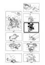
Sliding Fence (Fig. 15)
WARNING!
The sliding fence must be extended when
making any bevel cut. Failure to extend the sliding fence
will not allow enough space for the blade to pass through
which could result in serious injury. At extreme mitre or
bevel angles the saw blade may also contact the fence.
1. Unlock the fence cam locking lever (4) by pulling it
forward.
2. Extend the fence (2) by sliding it out to match the
degree of the bevel cut. Lock the fence cam locking lever
by pushing it in toward the fence.
NOTE:
When transporting the saw, always secure the
sliding fence in the collapsed position (pushing back the
lever).
NOTE:
Secure the sliding fence in position closest to
the saw blade when transporting the saw.
Sliding Carriage System (Fig. 17)
WARNING!
To reduce the risk of injury, return carriage
to the full rear position after each crosscut operation.
1. For a mitre cutting operations on small workpieces,
slide the cutting head assembly completely toward the rear
of the unit and tighten the silding carriage lock knob (1).
2. To cut wide boards up to 312 mm, the silding
carriage lock knob (1) must be loosened to allow the cutting
head to slide freely.
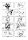
Chop Cut (Fig. 17)
1. Loosen the slide carriage lock handle (1) clockwise,
located on the side of the slide bar cover (2).
2. For a chop cutting operation on narrow workpieces,
slide the cutting head assembly to the desired position and
tighten the carriage lock handle counterclockwise .
3. To cut wide boards up to 312 mm, the carriage lock
handle should be loosened to permit the cutting head to
slide freely.
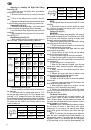
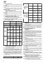
Mitre Cut (Fig. 18)
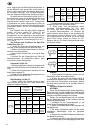
The sliding compound mitre saw is equipped with ten
positive mitre stops (1) on the saw base. The locations are
at 0, 15, 25, 31.6 and 45 degrees left and right, and 60°
right. These locations represent the most common angles
for cutting operation.
To make a mitre cut:
1. Unlock the mitre table by lifting up on the mitre
quickcam table lock (2).
2. While raising the positive stop locking lever (3) up ,
grasp the mitre handle (4) and rotate the mitre table left or
right to the desired angle.
3. Release the positive stop locking lever and set the
mitre at the desired angle making sure the lever snaps into
place.
NOTE:
The lever will only lock into place at one of the
ten positive stops.
4. Once the desired mitre angle is achieved, press
down on the quick cam mitre table lock to secure the table
into position.
5. If the mitre angle desired is NOT one of the ten
positive stops noted above, simply lock the table at the
desired angle by pressing down on the quick-cam mitre
table lock (2).
Bevel Cut (Fig. 19)
WARNING!
The sliding fence must be extended
to the left or right when making bevel cuts. The sliding
fences note three bevel angles where the user must
adjust the fences to match the degree of the bevel cut.
Failure to extend the sliding fence will not allow enough
space for the blade to pass through which could result in
serious injury. At extreme mitre or bevel angles the saw
blade may also contact the fence.
The right side sliding fence must be removed when
making any right bevel angle cuts greater than 35º in
combination with any right hand mitre angle. This fence
must also be removed whenever a 45º bevel angle is
desired with a mitre angle greater than 22.5º. Tilt the
cutting head to the desired angle as shown on the bevel
scale. The blade can be positioned at any angle, from a
90° straight cut (0° on the scale) to a 45° left and right
bevel. Tighten the lock handle (1) by pushing down to
lock the cutting head in position. Bevel positive stops are
provided at 0°, 33.9° and 45°.