13
retractable guard will lift and turn the broken line into a solid
red laser line.
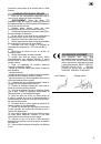
Laser Warning Label: Laser radiation does not view
directly with optical instruments class 1M laser product
<0.39mW, 400-700nm, CW, Acc.IEC 60825-1:2007
OPERATION OF LASER
With the blade assembly in the uppermost position:
1. Position your workpiece onto the mitre saw.
2. Turn on the mitre saw to activate the laser beam.
3. Verify the laser beam is aligned with the mark on the
workpiece.
WARNING!
Do not lower the blade assembly during
the alignment process.
4. If the mark on the workpiece is not aligned with the
dotted laser line, turn off machine, wait for the blade to stop
and reposition workpiece.
5. Turn on the mitre saw and verify alignment.
6. Once alignment is achieved, secure workpiece with
a clamping device and perform the cut.
VARIABLE SPEED SWITCH (Fig. 1) (Mod.
SRF305/1800E)
This saw is equipped with a variable speed control
dial (26). The blade stroke rate can be adjusted by
simply rotating the dial. To increase speed, rotate the dial
clockwise. To reduce speed, rotate the dial anti-clockwise.
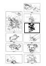
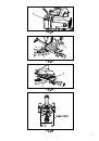
CHANGING BLADES (Fig. 25, 26, 27)
WARNING!
To avoid injury from accidental starting,
always turn the switch off and remove the power plug from
the power source before changing the blades.
Use correctly sharped saw blades. Observe the
maximum speed and tooth type marked on the saw blade.
Blade replacement procedure including the method for
repositioning that this must be carried out correctly. Do not
use a saw blade which is not recommended in this owner’s
manual.
Removing the Blade
1. Unplug the saw from the outlet
2. Raise the mitre saw to the upright position.
3. Raise the lower clear plastic blade guard (1) to the
uppermost position. (Fig. 25)
4. While holding the lower blade guard, loosen the
cover plate screw (2) with a Phillips screwdriver.
5. Rotate the cover plate (3) to expose the arbour bolt
(4).
6. Place the blade end wrench over the arbour bolt
7. Locate the arbour lock (5) on the motor, below the
belt cover. (Fig. 26)
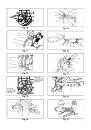
8. Press the arbour lock, holding it in firmly while
turning the blade clockwise. The arbour lock will then
engage and lock the arbour. Continue to hold the arbour
lock, while turning the wrench clockwise to loosen the
arbour bolt.
9. Remove the arbour bolt (5), the washers (8), the
laser collar (6), and the blade (7). Do not remove the inner
blade collar. (Fig. 27)
10. Raise the lower clear plastic blade guard (1) to the
upright position (Fig. 25) to remove the blade.
NOTE:
Pay attention to the pieces removed, noting
their position and direction they face. Wipe the blade
collars clean of any sawdust before installing a new blade.
Also, the 305 mm blade has a 25.4mm arbour hole with a
15.9 mm reducer to mount onto the saw.
Installing Blade
Un-plug the mitre saw before changing/installing the
blade.
1. Install a 305 mm blade with a 15.9 mm arbour (or a
25.4 mm arbour with a 15.9 mm reducer) making sure the
rotation arrow on the blade matches the clockwise rotation
arrow on the upper guard, and the blade teeth are pointing
downward.
2. Place the washer (8) against the blade (7), and then
also place the laser collar (6) and the other washer (8) in
turn on the arbour. Thread the arbour bolt (4) on the arbour
in a counterclockwise direction.
IMPORTANT:
Make sure the flats of the blade collars
are engaged with the flats on the arbour shaft. Also, the flat-
side of the laser collar must be placed against the blade.
3. Place the blade wrench on the arbour bolt.
4. Press the arbour lock (5), holding it in firmly while
turning the blade counterclockwise. When it engages,
continue to press the arbour lock in, while tightening the
arbour bolt (4) securely. (Fig. 26)
5. Rotate the cover plate (3) back to its original
position until the slot in the cover plate engages with the
cover plate screw (2). While holding the lower blade guard,
tighten the screw with a Phillips screwdriver. (Fig. 26)
NOTE:
The lower blade guard must be raised to the
upright position to access the cover plate screw.
6. Lower the clear retractable blade guard (1) and
verify the operation of the guard does not bind or stick. (Fig.
25)
7. Be sure the arbour lock is released so the blade
turns freely by spinning the blade until the arbour lock
disengages.
NOTE :
Make sure the collars are clean and properly
arranged. Lower the blade into the lower table and check
for any contact with the base or the turn table by spinning
the blade manually.
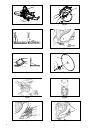
CHANGING THE BATTERIES (Fig. 28)
Unplug your saw.
Failure to unplug your saw could result in accidental
starting causing possible serious personal injury.
1. Remove the laser guide from the saw.
2. Loosen and remove the two screws, then remove
the laser guide cover.
3. Remove the three batteries as arrow on Fig. 28 and
replace new batteries.
4. Replace the laser guide cover and two screws and
tighten.
NOTE:
Replace the batteries with batteries that have
a rating of 1.5 volts (Number LR44).
When replacing the batteries, the battery cover should
be thoroughly cleaned. Use a soft paintbrush or similar
device, to remove all sawdust and debris.
CHANGING THE BELT (Fig. 29, 30)
Unplug your saw.
1. Loosen the bolts (1) and remove the belt cover.
2. Turn the screw (2) counter-clockwise with an Allen
wrench to move the motor to forward.
3. Remove and replace the belt.
4. Turn the screw (2) clockwise with an Allen wrench to
move the motor to rearward. Do not over tighten.
5. Replace the belt cover and tighten the bolts.
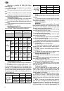
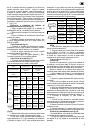
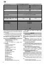
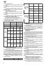
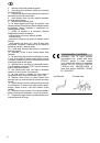
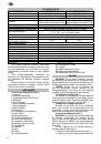
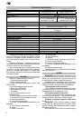
NOISE AND VIBRATION
WARNING!
Noise can be a health hazard. When
the noise level exceeds 80 dB(A), be sure to wear ear
protection.
The noise levels of this machine during cutting are as