Страница 6 из 65 GENERAL SAFETY RULES WARNING! Read all instructions. Failure to follow all instructions listed below may result in electric shock, fi re and/or serious injury. The term “power tool” in all of the warnings listed below refers to your mains operated (corded) power tool or battery operated (cordless)
Страница 7 из 65 - eye protection; - respiratory protection to reduce the risk of inhalation of harmful dust; - gloves for handling saw blades (saw blades shall be carried in a holder wherever practicable) and rough material. 12. The operator is adequately trained in the use adjustment and operation and operation
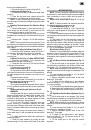
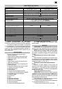
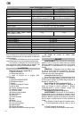
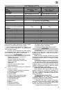
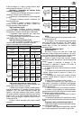
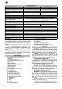
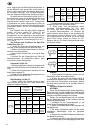
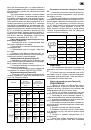
Страница 8 из 65 CHARACTERISTICS Motor No load speed Turn table TECHNICAL DATA SRF305/1800 1800 W, 230V~, 50 Hz -1 4200 min SRF305/1800E 1900 W, 230V~, 50 Hz 2000 - 4000 min-1 Ø342 mm Ø305mm;Ø30mm Bore;60T(ATB); Ø305mm;Ø30mm Bore;80T(TCG); Blade Ø305mm;Ø30mm Bore;80T(ATB) Ø305mm;Ø30mm Bore;80T(ATB) Blade thickness
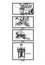
Страница 9 из 65 down to the collapsed position. 2. Push the lock pin (2) into the locking hole (3). Installing the Dust Bag (Fig. 4) 1. To install the dust bag (1), squeeze the metal collar wings (2). 2. Place the dust back neck opening around the exhaust port (3), and release the metal collar wings. NOTE: To
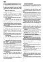
Страница 10 из 65 6. Repeat steps 3-5 until the blade is at 45° to the table. Once alignment is achieved, tighten the locknut (5 Fig. 12). 33.9° Bevel Adjustment (Fig. 12, 13, 14) 1. Set the mitre angle to zero degree. Fully extend both sliding fence. 2. Loosen the bevel lock handle (4 - Fig. 14) and tilt cutting
Страница 11 из 65 loss of power. To keep this to a minimum and to prevent overheating and motor burn-out, ask advice from a qualified electrician to determine the minimum wire size of the extension lead. If the power cable is broken, repair service is available at your nearest FELISATTI service centre. MOUNTING THE
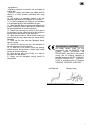
Страница 12 из 65 Removing or Installing the Right Side Sliding Fence (Fig. 19) 1. Unlock the fence cam-locking lever, and slide the sliding fence to the right. 2. Remove the hex screw (3) by a using a 3 mm hex key. 3. Lift up on the sliding fence to remove it from the saw. 4. Replace the sliding fence and thread
Страница 13 из 65 retractable guard will lift and turn the broken line into a solid red laser line. Laser Warning Label: Laser radiation does not view directly with optical instruments class 1M laser product <0.39mW, 400-700nm, CW, Acc.IEC 60825-1:2007 OPERATION OF LASER With the blade assembly in the uppermost
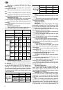
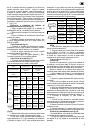
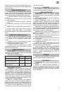
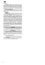
Страница 14 из 65 follows: SRF305/1800 SRF305/1800 E Acoustic pressure, dB(A) 100.3 89.4 Sound-power level, dB(A) 111.03 102.4 Vibration acceleration, m/s2 1.235 1.5 Use ear protection! WARNING! The vibration level given in these instructions has been measured in accordance with a standardized measurement procedure
Страница 15 из 65 NORMAS GENERALES DE SEGURIDAD ¡ATENCIÓN! Leer todas las instrucciones. El incumplimiento de cualquiera de las siguientes instrucciones puede provocar cortocircuitos eléctricos, incendios y/o lesiones graves. La expresión “herramienta eléctrica” que aparece en todas las siguientes advertencias se
Страница 16 из 65 de la herramienta eléctrica. ¡ADVERTENCIA! Rogamos leer las indicaciones de seguridad y las instrucciones, también las que contiene Instrucciones de servicio. MEDIDAS ESPECIALES DE SEGURIDAD 1. La sierra es adecuada sólo para cortar madera, metales no férreos y plásticos. ¡ADVERTENCIA! Utilice un
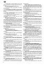
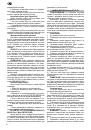
Страница 17 из 65 CARACTERÍSTICAS TÉCNICAS CARACTERÍSTICAS Motor Revoluciones de giro en vacío Mesa rotatoria Hoja Espesor de la hoja Espesor del dentado de la hoja Velocidad máxima de la hoja Grados del inglete SRF305/1800 1800 W, 230V~, 50 Hz 4200 min-1 SRF305/1800E 1900 W, 230V~, 50 Hz 2000 - 4000 min-1 Ø342mm
Страница 18 из 65 3. Ahora puede levantar el cabezal de corte lentamente hasta la posición superior. El cabezal de corte debe estar asegurado durante el transporte o el almacenamiento en la posición inferior. Para fijarlo en esa posición, proceda de la siguiente manera: 1. Pulsar la palanca de bloqueo (21, figura 1)
Страница 19 из 65 14) para ajustar el ángulo y mueva el brazo de corte en conjunto a la derecha. 3. Use un goniómetro para asegurarse que la hoja esté a un ángulo de 45º hacia la mesa de la máquina. 4. Para el ajuste mueva el brazo de corte en 0 °, afloje las tuercas de fijación (5, Figura 12) y gire el tornillo (6,
Страница 20 из 65 del conductor Zmax es <0,32 Ohm, no se puede esperar semejantes interferencias. (Si es necesario, puede solicitar información adicional a la compañía eléctrica local). Compruebe si el cable de alimentación y los dispositivos de salida utilizados son de conformidad con su sierra circular de mesa.
Страница 21 из 65 de 45° en sentido vertical en combinación con el bisel en sentido horizontal, mayor de 22,5°. Inclinar el cabezal de corte en el ángulo deseado, como se demuestra en la escala de cortes a inglete. La hoja de corte se puede ajustar a cualquier ángulo: desde el ángulo recto de 90° (0° en la escala)
Страница 22 из 65 2. Mientras sostiene el brazo de corte superior en esta posición, gire el botón de retención (1) hasta que alcance la placa de tope de limitación (2). 3. Compruebe la profundidad de corte una vez más haciendo un giro completo de adelante para atrás del mecanismo de corte. Láser rotativo La máquina
Страница 23 из 65 nada. 7. Asegúrese de que el botón de fijación de la hoja de corte esté liberado, de manera que la hoja de corte se pueda mover libremente. NOTA: Asegúrese de que el anillo interior del disco está limpio y bien instalado. Pulse el brazo de corte hacia abajo y asegúrese de que no hay contacto con la
Страница 24 из 65 NORMES GÉNÉRALES DE SÉCURITÉ ATTENTION! Lire toutes les instructions. Ne pas se conformer à toutes les instructions énumérées ci-dessous peut donner lieu à des secousses électriques, des incendies et/ou des lésions sérieuses. Le terme «outil électrique» de tous les avertissement énumérés ci-dessous
Страница 25 из 65 instructions, même celles qui se trouvent dans la Mode d’emploi. CONSIGNES SPÉCIFIQUES DE SÉCURITÉ 1. Cette scie est recommandée uniquement pour la coupe du bois, métaux non ferreux et plastique. ¡AVERTISSEMENT! Utiliser des lames TCG (impression rouge) de coupe pour métaux non ferreux et des
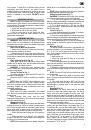
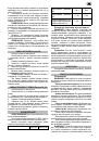
Страница 26 из 65 CARACTÉRISTIQUES TECHNIQUES SRF305/1800 SRF305/1800E 1800 W, 230V~, 50 Hz 1900 W, 230V~, 50 Hz -1 2000 - 4000 min-1 4200 min Ø342 mm Ø305mm;Ø30mm Alésage;60T(ATB); Ø305mm;Ø30mm Alésage;80T(ATB); Lame Ø305mm;Ø30mm Alésage;80T(ATB) Ø305mm;Ø30mm Alésage;80T(TCG) Epaisseur de lame 2 mm Epaisseur des
Страница 27 из 65 Lorsque vous transportez ou rangez la scie à onglet, la tête de coupe doit toujours être verrouillée en position basse : 1. Poussez la tête de coupe (1) jusqu’en position basse. 2. Engagez la goupille de blocage (2) dans l’encoche de verrouillage (3). Installation du sac à poussière (Fig. 4) 1.
Страница 28 из 65 3. En utilisant une équerre combinée, vérifiez que la lame est à 45° par rapport à la table. 4. Pour éventuellement la régler, inclinez la tête de la scie vers zéro degré, desserrez l’écrou de blocage (5 Fig. 12) puis vissez ou dévissez le boulon (6 - Fig. 12 ) en fonction de ce que vous souhaitez.
Страница 29 из 65 modification doit toujours être effectuée par un électricien qualifié. Cet équipement bénéficie d’une double isolation; il n’est donc pas nécessaire que l’alimentation soit reliée à la terre. AVERTISSEMENT! évitez tout contact avec les bornes de la fiche lors de son branchement sur la prise de
Страница 30 из 65 rallonge de la table à droite. 2. Dévisssez un ecrou à six pans (3) à l’aide d’une clef hexagonale. 3.Faites glisser la rallonge de la table dans la position désirée. 4.Remettez la rallonge de la table à sa place et fixez un ecrou à six pans (3) si vous ne faites pas des coupes en biseau de droite.
Страница 31 из 65 position, faites tourner l’ergot d’arrêt (1) jusqu’à ce qu’il entre en contact avec la plaque d’arrêt (2). 3. Revérifiez la profondeur de la lame en déplaçant la tête de coupe d’avant en arrière sur toute la course d’une coupe classique le long du bras de contrôle. Guidage laser Votre outil est
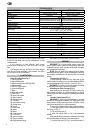
Страница 32 из 65 et correctement disposés. Abaissez la lame dans la table inférieure puis faites-la tourner à la main afin de vérifier qu’elle n’entre pas en contact avec l’embase ou la table pivotante. REMPLACEMENT DES PILES (Fig. 28) Débranchez la scie, sous peine d’entraîner un démarrage accidentel et de
Страница 33 из 65 NORME DI SICUREZZA GENERALE ATTENZIONE! Leggere tutte le istruzioni. La mancata ottemperanza a tutte le istruzioni sotto elencate può dare luogo a scosse elettriche, incendi e/o lesioni serie. Il termine “utensile elettrico” di tutte le avvertenze elencate qui sotto si riferisce agli utensili
Страница 34 из 65 5. Sostituire l’inserto del pianale se logorato. 6. Usare dischi del costruttore e soltanto se corrispondo alla norma EN 847-1. 7. Collegare alla sega circolare a pianale con attrezzo di aspirazione polvere nel corso di taglio. 8. Usare soltanto dischi, che sono adatti al materiale, che deve essere
Страница 35 из 65 CARATTERISTICHE Motore Giri a folle Massa rotante Disco di taglio Spessore del disco tagliente Spessore dei denti del disco Velocità massimale del disco di taglio Gradi dell’inclinazione CARATTERISTICHE TECNICHE SRF305/1800 SRF305/1800E 1800 W, 230V~, 50 Hz 1900 W, 230V~, 50 Hz 4200 min-1 2000 -
Страница 36 из 65 e la leva di bloccaggio (21, fig.1). 2. Estrarre il pulsante di fissaggio (2) all’esterno. 3. Allora è possibile sollevare lentamente la testa di taglio in posizione alta. La testa di taglio deve essere bloccata in corso di trasporto o in conservazione in posizione bassa. Per fissarla del modo,
Страница 37 из 65 NOTA: All’estrazione della manopola fissante potrebbe richiedere lo spostamento a destra e sinistra del braccio. 2. Liberare la manovella a fissaggio veloce (4, fig. 14) per regolazione dell’angolo e spostare il kit del braccio di taglio a destra. 3. Usare goniometro per accertarsi, che il disco di
Страница 38 из 65 di una lampada). Se la resistenza del conduttore Zmax e < 0.32 Ohm, non si possono aspettare tali disturbi (Se necessario, richiedere informazione complementare dalla Vs società di distribuzione elettrica). Verificare se il cavo di alimentazione e gli attrezzi d’uscita usati corrispondono alla Vs
Страница 39 из 65 la leva di fissaggio (1) in basso. Limitaotri fissati di taglio sotto inclinazione esistono 0°, 33,9° e 45°. Rimozione o installazione del limitatore destro verticale a slittamento (fig.19) 1. Liberare la leva di fissaggio del limitatore verticale a slittamento e slittare verso la parte destra. 2.
Страница 40 из 65 2. Mentre mantenete il braccio superiore tagliante in questa posizione, girare il pulsante di fissaggio (1) finché raggiunge la superficie limitante (2). 3. Verificare, ancora una volta, la profondità di taglio, compiendo movimento completo da avanti - indietro del meccanismo di taglio. Laser
Страница 41 из 65 di taglio e accertarsi, che manca qualsiasi contatto con il telaio metallico o la massa rotante, girando leggermente il disco con la mano. SCAMBIO BATTERIE (Fig.28) La spina del cavo di alimentazione dello strumento elettrico deve ritirarsi dalla presa prima dello scambio batterie, perché in caso
Страница 42 из 65 ALLGEMEINE SICHERHEITSBESTIMMUNGEN ACHTUNG! Es sind alle Anweisungen zu lesen. Bei Nichtbeachtung nachstehender Anweisungen kann es zu Stromschlägen, Bränden und/oder schweren Verletzungen kommen. Der Begriff „Elektrowerkzeug“ in allen untenstehenden Hinweisen bezieht sich auf die netz- (mit Kabel)
Страница 43 из 65 SPEZIELLE SICHERHEITSWARNUNGEN 1. Diese Säge ist ausschließlich zum Sägen von Holz, NE-Metall und Kunststoff geeignet. WARNUNG! Verwenden Sägeblätter TCG (rotem Aufdruck) zum Schneiden Nichteisen und Kunststoffl, verwenden Sägeblätter ATB (schwarzer Druck) zum Schneiden von Holz. 2. Verwenden Sie
Страница 44 из 65 CHARACTERISTICS Motor Leerlaufdrehzahl Drehtisch TECHNISCHE DATEN SRF305/1800 1800 W, 230V~, 50 Hz -1 4200 min SRF305/1800E 1900 W, 230V~, 50 Hz 2000 - 4000 min-1 Ø342 mm Ø305mm;Ø30mm Bohrung;60T(ATB); Ø305mm;Ø30mm Bohrung;80T(TCG); Ø305mm;Ø30mm Bohrung;80T(ATB) Ø305mm;Ø30mm Bohrung;80T(ATB) Dicke
Страница 45 из 65 3. Jetzt können Sie den Sägekopf langsam in die obere Stellung fahren lassen. Den Sägearm sollten Sie beim Transport bzw. bei der Aufbewahrung immer in der unteren Stellung arretieren. Um den Sägearm in die untere Stellung zu arretieren, gehen Sie wie folgt vor: 1. Drücken Sie den Sägearm (1) nach
Страница 46 из 65 nach rechts heraus und danach ziehen Sie den Arretierungshebel (1 - Abb. 12) heraus. HINWEIS: Wenn Sie den Arretierungshebel herausziehen, kann es erforderlich sein, dabei den Sägearm nach links/ rechts zu bewegen. 2. Lösen Sie den vorderen Schnellarretierungshebel (4 - Abb. 14) für die
Страница 47 из 65 (1). Breite Stücknotwendigkeit upfront Unterstützungen 1. Rotate die zwei stützt upfront (1) in Richtung zur Rückseite der Säge. HINWEIS: Diese Unterstützungen (1) sollten in die 0 Position wie in Fig.32 gesetzt werden, bevor man transportiert gezeigt. ANSCHLUSS AN DIE STROMQUELLE Durch schlechten
Страница 48 из 65 muss. Vergisst man die Hilfsanschläge auszuziehen, so hat das Sägeblatt nicht genug Platz um frei laufen zu können, was zu ernsthaften Verletzungen führen kann. Bei extremen Gehrungs- oder Schrägschnittwinkeln kann das Sägeblatt außerdem den Anschlag berühren. Bei jedem rechten Winkelschnitt größer
Страница 49 из 65 vorne, bis die Mitte des Sägeblattes gerade über dem Werkstück steht. 6. Betätigen Sie den Schalter (6) um die Säge einzuschalten. 7. Wenn die Säge Ihre volle Geschwindigkeit erreicht hat, drücken Sie den Griff (3) langsam herunter und sägen das Werkstück (5) langsam an. 8. Bewegen Sie den Griff
Страница 50 из 65 2. Stecken Sie den Ring (8) in die Sägeblattwelle, die Laser-Dornmanschette (6) auf die Sägeblattwelle, den Ring (8) so dass diese gegen das Blatt drückt. Schrauben Sie nun die Sägeblattschraube entgegen dem Uhrzeigersinn fest. (Abb. 27) Wichtig: Stellen Sie sicher, das die abgeflachten Seiten der
Страница 51 из 65 fest angezogen sind, und ziehen Sie eine lose Schraube sofort wieder fest an. Dies könnte sonst eine ernsthafte Gefahr darstellen. - Wartung des Motors: Achten Sie darauf, dass kein Öl oder Wasser in den Motor eindringen kann. - Ersatz der Kohlebürsten: Wenden Sie sich zur Durchführung des
Страница 52 из 65 ОБЩИЕ ПРАВИЛА ПО ТЕХНИКЕ БЕЗОПАСНОСТИ ВНИМАНИЕ! Прочтите все предупреждения и указания мер безопасности и все инструкции. Невыполнение предупреждений и инструкций может привести к поражению электрическим током, пожару и (или) серьезным повреждениям. Сохраните все предупреждения и инструкции для
Страница 53 из 65 ся частей, поломки деталей и иных несоответствий, которые могут повлиять на работу машины. В случае неисправности отремонтируйте машину перед использованием. Часто несчастные случаи происходят из-за плохого обслуживания машины. f) Храните режущие инструменты в заточенном и чистом состоянии. Режущие
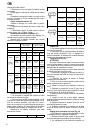
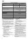
Страница 54 из 65 ТЕХНИЧЕСКАЯ ИНФОРМАЦИЯ ХАРАКТЕРИСТИКИ Мотор Скорость вращения на холостом ходу Поворотный стол Диск Толщина диска Толщина зубьев Максимальная скорость диска Фиксатор регулировки угла поворота SRF305/1800 1800 Вт, 230 В~, 50 Гц 4 200 мин-1 SRF305/1800E 1900 Вт, 230 В~, 50 Гц 2000 - 4000 мин-1 Ø342
Страница 55 из 65 щим образом: 1. Нажмите на рукоятке пильного блока (1) кнопку блокировки защитного кожуха (3 рис.1). 2. Вытащите фиксатор нижнего положения пильного блока (2). 3. Поднимите пильный блок в верхнее положение. Для опускания пильного блока поступайте следующим образом: 1. Нажмите на рукоятке пильного
Страница 56 из 65 от содержимого, открыв замок молнии. • Горизонтальное перемещение пильного блока (Рис.1) Горизонтальное перемещение пильного диска (18) осуществляется за рукоятку (4) и фиксируется винтом (1 рис.2). • Установка угла наклона (Рис.1) Угол наклона пильного диска (18) как вправо, так и влево
Страница 57 из 65 часто используемых отметок углов резки есть ограничители, позволяющие быстро настроить стол на нужное положение. Следуйте описанным ниже инструкциям для осуществления быстрых и точных настроек. 1. Поднимите быстрозажимной фиксатор поворота для разблокировки стола. 2. Для установки индикатора (2) на
Страница 58 из 65 противном случае существует возможность поражения электрическим током. В случае недостаточной подачи питания от электрических сетей при включении оборудования могут происходить небольшие перепады напряжения. Это может оказать негативные последствия и на другое оборудование (например, мерцание лампы
Страница 59 из 65 места для прохождения диска, что может привести к серьезным травмам. Кроме того, в крайних положениях для пропилов под углом или под наклоном диск может касаться упора. При осуществлении пропилов с наклоном вправо более 35° в сочетании с правосторонним пропилом под любым углом необходимо снять упор
Страница 60 из 65 передний край заготовки. 8. Медленно продвигайте рукоятку по направлению к упору, завершая пропил. 9. Отпустите курок и дайте диску полностью остановиться, прежде чем поднимать головку. Настройка глубины реза (Рисунок 24) Можно настроить глубину реза для ровных и повторяющихся неглубоких надпилов.
Страница 61 из 65 Когда шпиндельный зажим установится, продолжайте удерживать его и затяните шпиндельный болт (4) до упора. (Рисунок 26) 5. Чтобы вернуть крышку (3) в исходное положение, поворачивайте ее до тех пор, пока отверстия в крышке не совместятся с винтом на крышке(2). Удерживая нижнее ограждение диска,
Страница 62 из 65 мастерских. При хранении пила не должна подвергаться воздействию влаги и химически активной в отношении материалов среды. Храните пилу в месте, недоступном для детей при положительной температуре окружающей среды, но не выше +40°С и относительной влажности воздуха не более 80%. При транспортировке
Страница 64 из 65 Interskol Power Tools S.L. Carretera de Sant Joan de les Abadesses s/n17500 RIPOLL, (Girona), SPAIN Tel +34972700200 Fax +34972700554 e-mail: felisatti@interskol.es