9
2.5
Tape measure, tape measure
clamp
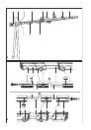
– Insert the tape measure (5.1) into the
extendable end piece.
– Guide the tape measure (5.2) through the
top grooves on the extendable end piece,
the adjustable spacer and the stop profi le
in succession.
– Unscrew the rotary knob (5.4) for the tape
measure clamp.
– Insert the slot nut for the tape measure
clamp into the slot (5.3) on the stop pro-
fi le.
– Secure the tape measure clamp towards
the end of the tape measure by tightening
the rotary knob (5.4).
2.6 Support
plate
The support plate (1.4) is used to support
longer workpieces.
– Screw the rotary knob (6.5) through the
recess (6.4) and into the slot nut (6.1) in
the slot (6.2) on the stop profi le to secure
the support plate. Note: The two cams
(6.3) must slot into the groove (6.2).
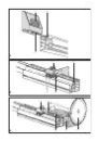
2.7 Support
The support (1.3) is used to support taller
workpieces.
– Unscrew the rotary knob (7.1) that clamps
the support.
– Insert the slot nut (7.3) into the top slot
(7.2) on the stop profi le or the adjustable
spacer.
– Slide the support to the required positi-
on.
– Tighten the rotary knob (7.1) to secure the
support.
2.8 Stop
fl ag
The stop fl ag (1.5) is used to adjust the
distance between the saw blade and the
workpiece so that the workpiece is cut to
the required length.
– Unscrew the rotary knob (1.11) on the
adjustable spacer.
– Move the stop profi le (1.1) and the spacer
(1.6) approx. 8 cm apart.
– Unscrew the rotary knob (8.1) that clamps
the stop fl ag.
– Insert the slot nut (8.3) into the top slot
(8.2) on the stop profi le or the adjustable
spacer.
– Slide the stop fl ag to the required positi-
on.
– Tighten the rotary knob (8.1) to secure the
stop fl ag.
Adjusting play on the stop fl ag
– Turn (tighten or unscrew) the two screws
(8.4) until the stop fl ag moves smoothly
along the slot, but without play.
3 Adjustments
3.1 Tape
measure
The tape measure starts at 30 cm so that
it does not come into contact with the saw
blade. Therefore, make sure that the dis-
tance between the tape measure and the
saw blade is correct:
– Set both the horizontal and vertical mitre
angles on the KS 120 to 0°.
– Place a workpiece (9.4) with a length of
450 mm on the KS 120 lengthways against
the saw blade (9.3).
– Slide the stop fl ag (9.1) up to the workpi-
ece. Clamp the stop fl ag in this position.
– Unscrew the rotary knob for the measuring
tape clamp (9.5).
– Move the tape measure until the measu-
rement at the edge (9.2) of the stop fl ag
indicates 450 mm.
– Use the tape measure clamp (9.5) to se-
cure the tape measure in this position. The
tape measure now indicates the exact dis-
tance to the saw blade. The measurement
at the edge (9.2) is the distance between
the stop fl ag and the saw blade.
3.2 Length
adjustment
Unscrew the rotary knob (1.12) to extend
and retract the end piece (1.7). The maxi-
mum extension length is 2300 mm.
Unscrew the rotary knob (1.11) to move
the spacer.
4 Working
To trim a workpiece to a certain length, pro-
ceed as follows:
– Adjust the stop fl ag to the required dimen-
sion.
– Place the workpiece against the stop
fl ag.
– Cut through the workpiece with the
KS 120.