8
English
INSTALLING AND REMOVING BITS
WARNING
Be sure to switch power OFF and disconnect the
plug from the receptacle to avoid serious trouble.
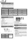
1. Installing bits
(1) Clean and insert shank of bit into the collet chuck
until shank bottoms, then back it out approximately
2 mm.
(2) With the bit inserted and pressing the lock pin
holding the armature shaft, use the 23 mm wrench
to firmly tighten the collet chunk in a clockwise
direction (viewed from under the router). (Fig. 1)
CAUTION
䡬
Ensure that the collet chuck is firmly tightened after
inserting a bit. Failure to do so will result in damage
to the collet chuck.
䡬
Ensure that the lock pin is not inserted into the
armature shaft after tightening the collet chuck.
Failure to do so will result in damage to the collet
chuck, lock pin and armature shaft.
(3) Be sure to use a chuck sleeve when using a 6 mm
bit with a collet chuck capacity of 8 mm. First insert
the chuck sleeve deeply in the collet chuck, then
insert the bit in the chuck sleeve. Tighten the collet
chuck firmly as in step (1) and (2).
2. Removing Bits
When removing the bits, do so by following the
steps for installing bits in reverse order.
CAUTION
Ensure that the lock pin is not inserted into the
armature shaft after tightening the collet chuck.
Failure to do so will result in damage to the collet
chuck, lock pin and armature shaft.
HOW TO USE THE ROUTER
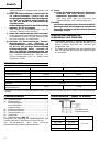
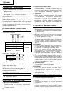
1. Adjusting depth of cut (Fig. 2)
(1) Use stopper pole to adjust depth of cut.
1
Place the tool on a flat wood surface.
2
Turn the stopper block so that section to which the
cutting depth setting screw on a stopper block is
not attached comes to the bottom of the stopper
pole. Loosen pole lock knob allowing the stopper
pole to contact with stopper block.
3
Loosen the lock lever and press the tool body until
the bit just touches the flat surface. Tighten the lock
lever at this point. (Fig. 3)
4
Tighten pole lock knob. Align the depth indicator
with the “0” graduation of scale.
5
Loosen pole lock knob, and raise until indicator
aligns with the graduation representing the desired
cutting depth. Tighten pole lock knob.
6
Loosen the lock lever and press the tool body down
until the stopper block to obtain the desired cutting
depth.
(2) As shown in Fig. 4 (a), loosening the two nuts on
the threaded column and moving then down will
allow you to move down to the end position of the
bit when the lock lever is loosened. This is helpful
when moving the router to align the bit with the
cutting position.
As shown in Fig. 4 (b), tighten the upper and lower
nuts to secure the cutting depth.
(3) When you are not using the scale to set the cutting
depth, push up the stopper pole so that it is not
in the way.
2. Stopper block (Fig. 5)
The 2 cut-depth setting screws attached to the
stopper block can be adjusted to simultaneously set
3 different cutting depth. Use a wrench to tighten
the nuts so that the cut-depth setting screws do not
come loose at this time.
3. Guiding the router
WARNING
Be sure to switch power OFF and disconnect the
plug from the receptacle to avoid serious trouble.
(1) Template Guide
Use the template guide when employing a template
for producing a large quantity of identifically shaped
products.
As shown in Fig. 6, secure the template guide to
the base of the router with two accessory screws.
At this time, ensure that the projection side of the
template guide is facing the bottom surface of the
base of the router.
A template is a profiling mold made of plywood
or thin lumber.
When making a template, pay particular attention
to the matters described bellow and illustrated in
Fig. 7.
When using the router along the interior plane of
the template, the dimensions of the finished product
will be less than the dimensions of the template
by an amount equal to dimension “A”, the difference
between the radius of the template guide and the
radius of the bit. The reverse is true when using
the router along the exterior of the template.
Secure the template to the workpiece. Feed the
router in the manner that the template guide moves
along the template as shown in Fig. 8.
(2) Straight guide (Fig. 9)
Use straight guide for chamfering and groove cutting
along the materials side.
1
Insert the guide bar into the hole in the bar holder,
then lightly tighten the 2 wing bolts (A) on top of
the bar holder.
2
Insert the guide bar into the hole in the base, then
firmly tighten the wing bolt (A).
3
Make minute adjustments of the dimensions between
the bit and the guide surface with the feed screw,
then firmly tighten the 2 wing bolts (A) on top of
the bar holder and the wing bolt (B) that secures
the straight guide.
4
As shown in Fig. 10, securely attach the bottom of
the base to processed surface of the materials. Feed
the router while keeping the guide plane on the
surface of the materials.
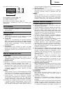
4. Adjusting the rotation speed (Model M8V2 only)
The M8V2 has an electronic control system that
allows stepless rpm changes.
As shown in Fig. 11, dial position “1” is for minimum
speed, and position “6” for maximum speed.
5. Cutting
CAUTION
䡬
Wear eye protection when operating this tool.
䡬
Keep your hands, face and other body parts away
from the bits and any other rotating parts, while
operating the tool.