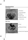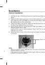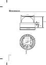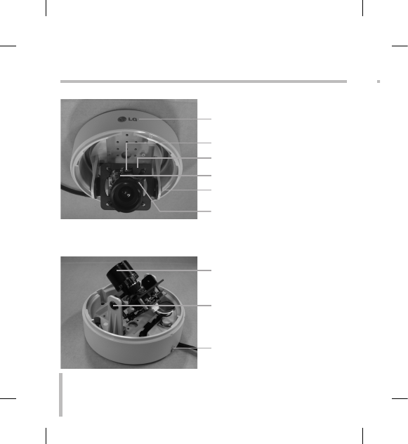
Front View
Side View
Pan Base
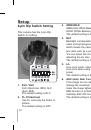
6-pin Dip Switch
Tilt Base
Zoom Lever
Tilting Lock Screw
Focus Lever
Lens
Tilting Lock Screw
Dome Cover Separatory Spring
8
Construction
Installation
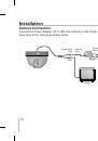
Camera Installation
1. Aim the LG logo of the Dome Camera to face the place that you wish to
watch.
. Tighten the M4 Tapping Screws to fix the Dome Camera on the ceiling,
then adjust the Pan(Left/Right) by moving the Pan Base. Tighten the
M4 Tapping Screws after adjustment.
3. Loosen the Tilting Lock Screw. Adjust the Tilt(Up/Down) by moving the
Tilt Base then tighten Tilting Lock Screw.
4.
Set the Zoom Lever to a point between "Tele" and "Wide" to choose the
desired angular field of view.
Set the Focus Lever to a point between "Near" and "Far" to choose the
desired focus of view.
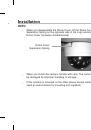
5. Install the Dome Cover to the main body by turning it counterclockwise
to the end.
Notes
• When you install the camera, handle with care. The camera could be damaged by
improper handling or storage.
• If this camera is mounted on the other places except ceiling, you need an extra
bracket for mounting. (not supplied)