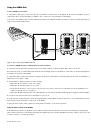
GSR Speakers Guide
10
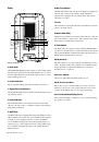
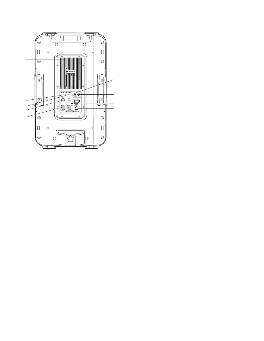
Back
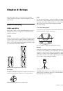
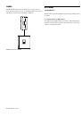
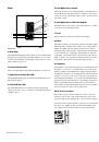
1 Heat Sink
The aluminum amplifier panel doubles as a heat sink, which
dissipates heat generated by the GSR amplifier. Do not block
the heat sink, and make sure nothing comes in direct contact
with it while powered on.
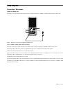
2 Power Indicator
The Power LED lights green when the GSR is powered on.
3 Signal Present Indicator
The Signal LED lights green to indicate when the GSR is receiv-
ing an input signal.
4 Peak Indicator
The Peak LED flashes red to indicate that the speaker has
clipped; lower the source, or turn the speaker down using its
back panel Level knob.
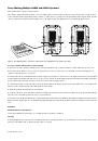
5 HPF 75Hz
The HPF 75Hz button engages/disengages the high-pass filter
(HPF). When pressed (button is “in”), the GSR speaker engages
a 24 dB per octave high-pass filter to reduce or eliminate
low-end rumble being picked up by microphone inputs (or
any noise below 75Hz). When you’re also using a GSR18 sub,
we recommend engaging the HPF on all satellite GSR10 or
GSR12 speakers.
6 Mic/Line Button
The Mic/Line button lets you choose an Input operating level
between Mic or Line levels. When a single XLR micro-
phone/cable is plugged into the GSR speaker, this switch
should be set to Mic.
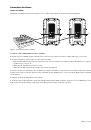
7 Level
The Level knob controls the amount of attenuation or gain ap-
plied to the input signal.
8 Input (XLR/TRS)
The Input jack is where you connect a microphone, or the out-
puts from a mixer or other device. This jack allows for either
XLR or TRS (1/4-inch) input connections.
9 Thru Output
The Thru jack is an output for daisy-chaining multiple GSR
speakers. Use an XLR cable to connect this Thru jack to the In-
put on another GSR10 or GSR12. The Thru output bypasses (is
unaffected by) HPF and Mode selection.
10 Mode Knob
The Mode knob lets you select among four different presets to
“tune” the GSR speaker and optimize its performance in dif-
ferent situations. For more information, see “Modes for
Speaker Presets” on page 11.
11 Power Switch
The Power switch turns the GSR speaker on/off.
12 AC Power and Fuse
This socket accepts a standard IEC power cable (one is in-
cluded) for AC power to the speaker. The fuse protects the
speakers from damage due to power spikes and surges.
13 Pole Mount Stabilizing Screw
This secures the GSR10 or GSR12 to a pole, when mounting
the speaker on a stand.
GSR10 / GSR12 back
1
2
3
4
5
6
7
8
9
10
11
12
13