3
Features
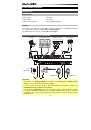
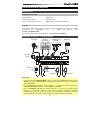
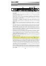
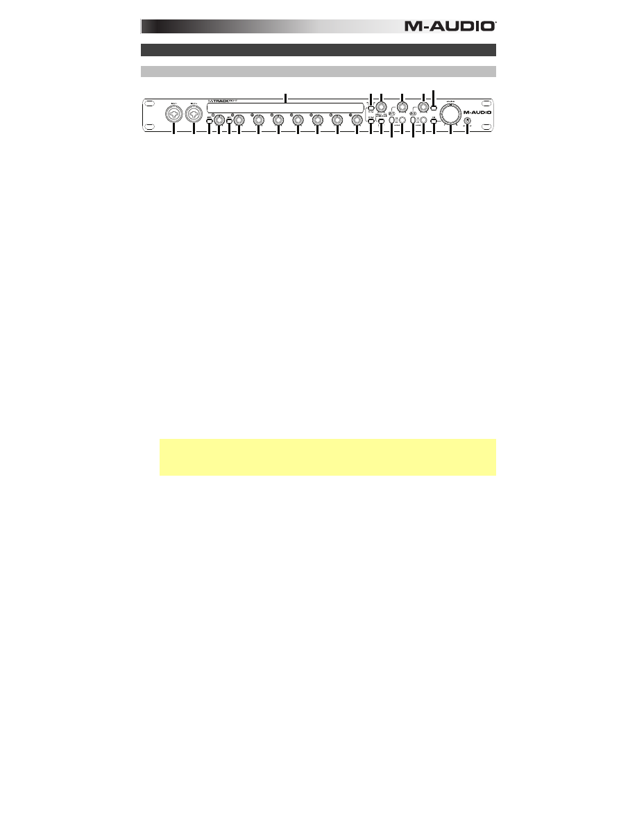
Front Panel
1
3 3
5
6 6 5 5 5 5 5 5 5 4 8
9
9 13 14
10 10
2
4 7 11 1112
1.
Power Mode Button:
Use this button to switch M-Track Eight between its power modes:
When the edges of the display are lit, M-Track Eight is powered on. To power M-Track Eight
on, press this button once.
When a leaf icon is shown in the display, M-Track Eight is in Standby Mode (a low-power
mode). To put M-Track Eight in Standby Mode, either press and hold this button for two
seconds (when it is powered on) or wait for 30 minutes after your computer enters its
"sleep"/low-power mode.
When the display is completely off, M-Track Eight is powered off. M-Track Eight will power-off
automatically after not detecting a connection to your computer for 30 minutes. You do not
need to enter this mode manually; Standby Mode draws only a small amount of power.
2.
Display:
This display shows the signal level of the eight inputs. The edges of the display will
light up when M-Track Eight is powered on. A leaf symbol will light up when M-Track Eight is in
standby mode.
3.
Inputs 1–2:
Connect microphones, line-level devices, or guitars to these inputs with an XLR or
1/4" TRS cable. (For mic-level signals, use an XLR cable. For line-level signals, use a 1/4" TRS
cable.) View the input signal levels in the display.
4.
+48V Switch:
This switch activates and deactivates phantom power for Channels 1–4 and/or
Channels 5–8. When activated, phantom power supplies +48V to the corresponding XLR mic
inputs. Please note that dynamic microphones and ribbon microphones do not require
phantom power, while most condenser microphones do. Consult your microphone's
documentation to find out whether it needs phantom power.
5.
Input Gain:
Adjusts the input's gain level. Set this knob so the corresponding level meter in
your DAW displays a "healthy" level during performance—but not so high that the meter "clips"
or peaks, causing distortion in the audio.
6.
Instrument Selector:
When the switch is in the raised position, the channel will accept
microphone- or line-level signals. When this switch is in the depressed position, the channel will
serve as a high-impedance input for connecting guitar or bass instruments.
7.
Monitor Mix:
Blends any amount of zero-latency signal from all your inputs (
Direct
) with the
output of your computer (
USB
).
Note:
When set to
Direct
, the left channel will be a sum of
Inputs 1
,
3
,
5
, and
7
and the right
channel will be a sum of
Inputs
2
,
4
,
6
, and
8
. You can sum these left and right channels (to
hear all inputs as a single summed mono signal) by putting the
Direct Mono
or
Mono
button in
its depressed position.
This knob is useful during recording when dealing with the "buffer size" and "latency." The
computer takes a short amount of time to process the incoming audio before sending it back
out; this time is determined by the buffer size setting. Latency is the resulting delay between
the incoming sound (playing your instrument, singing, etc.) and outgoing sound (when you hear
it in the DAW). Higher buffer sizes result in higher latency.
If your computer is powerful enough, you may be able to set your buffer size low enough such
that you may never need direct monitoring. In this case, set the knob all the way to the
USB
position to monitor only the audio output of your DAW.
In other cases, though, low buffer sizes can consume a lot of your computer's CPU and cause
audio glitches, so you may need to use a higher buffer setting, resulting in latency. In this case,
use a higher buffer size and turn the knob more towards the
Direct
position to monitor your
incoming signal without latency. When listening to the playback, turn it all the way to the
USB
position.