M-Audio Studiophile DSM1 Guide
4
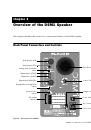
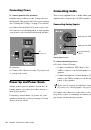
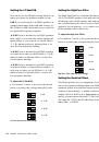
Power Connections
AC Connector and Power Switch
The AC connector accepts a standard modular
AC power cord. One power cord is included with
your speaker. Use the Power switch to turn the
speaker on or off.
Voltage Selector
Before connecting a DSM1 speaker to a power
source, make sure the Voltage Selector setting
matches your local voltage (100–120V or
220–240V).
Fuse
The fuse protects components of the DSM1
speaker from being damaged by electrical under-
or over-powering, spikes, and other anomalies.
A 2.5 Amp fuse is required for both the
100–120V and the 220–240V settings.
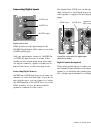
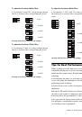
Inputs
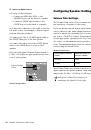
Input Selector Switch
The input selector switch selects between the
following input states for the speaker:
Analog
Activates the analog inputs of the
speaker.
Digital
Activates the digital inputs of the
speaker.
Digital Standby
Activates the digital inputs of
the speaker, but automatically puts the speaker
in a low-power standby mode when the digital
clock signal is lost for more than one second (for
example, when the digital source is powered
off). When the clock signal is restored, the
speaker wakes up from standby mode.
Analog Inputs
The DSM1 speaker provides an XLR analog in-
put connector and a balanced 1/4-inch TRS ana-
log input connector.
The analog input signal is converted to a
96 kHz, 24-bit digital signal for crossover/EQ
processing, and converted back to analog just
prior to the power stage of the driver amplifiers.
Signals may be sent to the two analog input con-
nectors at the same time. When two analog in-
put signals are present, they are summed.
XLR Connector
The XLR Analog In connector is balanced. (If the
signal source is unbalanced, connect the unused
pin to ground.)
1/4-inch TRS Connector
The 1/4-inch TRS Analog In connector is bal-
anced. (If the signal source is unbalanced, con-
nect the unused pin to ground.)
Analog Input Sensitivity Switch
The analog input operating level can be
switched between –10 dBV and +4 dBu. This set-
ting applies to both the XLR and 1/4-inch TRS
analog inputs. For information on the appropri-
ate operating level for your audio source, see the
manufacturer’s specifications.
Make sure to use a fuse rated at 2.5 Amps.
Do not use fuses of any other rating, or you
risk damage to the unit