7
tool may be damaged.
•
Use the knob after the tool comes to a complete
stop.
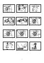
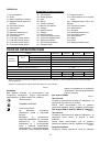
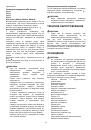
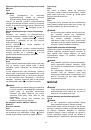
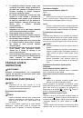
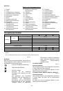
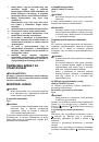
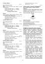
For models HR2810, HR2810T, HR2811F, HR2811FT
Rotation with hammering
Fig.7
For drilling in concrete, masonry, etc., rotate the action
mode changing knob to the
symbol. Use a
tungsten-carbide tipped bit.
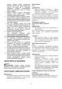
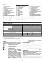
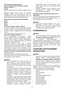
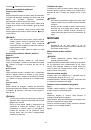
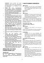
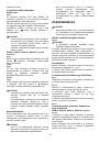
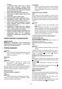
Rotation only
Fig.8
For drilling in wood, metal or plastic materials, lock
button and rotate the action mode changing knob to the
symbol. Use a twist drill bit or wood bit.
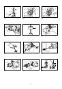
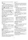
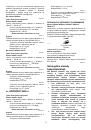
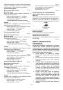
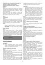
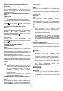
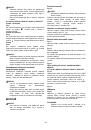
Hammering only
Fig.9
For chipping, scaling or demolition operations, rotate the
action mode changing knob to the
symbol. Use a
bull point, cold chisel, scaling chisel, etc.
CAUTION:
•
Do not rotate the action mode changing knob when
the tool is running under load. The tool will be
damaged.
•
To avoid rapid wear on the mode change
mechanism, be sure that the action mode
changing knob is always positively located in one
of the three action mode positions.
Torque limiter
The torque limiter will actuate when a certain torque
level is reached. The motor will disengage from the
output shaft. When this happens, the bit will stop turning.
CAUTION:
•
As soon as the torque limiter actuates, switch off
the tool immediately. This will help prevent
premature wear of the tool.
•
Bits such as hole saw, which tend to pintch or
catch easily in the hole, are not appropriate for this
tool. This is because they will cause the torque
limiter to actuate too frequently.
ASSEMBLY
CAUTION:
•
Always be sure that the tool is switched off and
unplugged before carrying out any work on the
tool.
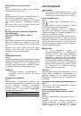
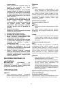
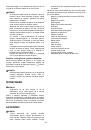
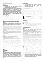
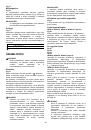
Side grip (auxiliary handle)
Fig.10
CAUTION:
•
Always use the side grip to ensure operating
safety.
Install the side grip so that the teeth on the grip fit in
between the protrusions on the tool barrel. Then tighten
the grip by turning clockwise at the desired position. It
may be swung 360° so as to be secured at any position.
Bit grease
Coat the bit shank head beforehand with a small amount
of bit grease (about 0.5 - 1 g).
This chuck lubrication assures smooth action and longer
service life.
Installing or removing the bit
Fig.11
Clean the bit shank and apply bit grease before installing
the bit.
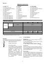
Fig.12
Insert the bit into the tool. Turn the bit and push it in until
it engages.
After installing, always make sure that the bit is securely
held in place by trying to pull it out.
To remove the bit, pull the chuck cover down all the way
and pull the bit out.
Fig.13
Bit angle (when chipping, scaling or
demolishing)
For models HR2810, HR2810T, HR2811F, HR2811FT
Fig.14
The bit can be secured at the desired angle. To change
the bit angle, rotate the action mode changing knob to
the
O
symbol. Turn the bit to the desired angle.
Rotate the action mode changing knob to the
symbol.
Then make sure that the bit is securely held in place by
turning it slightly.
Fig.15
Depth gauge
Fig.16
The depth gauge is convenient for drilling holes of
uniform depth. Loosen the side grip and insert the depth
gauge into the hole in the side grip. Adjust the depth
gauge to the desired depth and tighten the side grip.
NOTE:
•
The depth gauge cannot be used at the position
where the depth gauge strikes against the gear
housing.
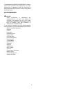
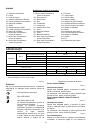
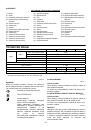
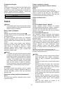
Dust cup
Fig.17
Use the dust cup to prevent dust from falling over the
tool and on yourself when performing overhead drilling
operations. Attach the dust cup to the bit as shown in the
figure. The size of bits which the dust cup can be
attached to is as follows.
Bit diameter
Dust cup 5
6 mm - 14.5 mm
Dust cup 9
12 mm - 16 mm
006406