18
Chapter 4 –
MITICO and Peripherals Overview
4.4
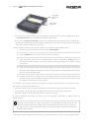
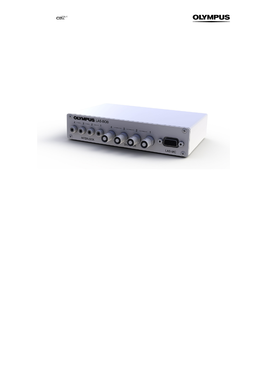
The LAS-BOB Laser Safety Break-out Box
It features on the front panel
—
Four INTERLOCK 4 – 3 – 2 – 1 cinch plugs to connect it with the INTERLOCK connectors of
Olympus Soft Imaging Solutions laser systems (Other lasers may need adaptors.)
—
Four SHUTTER 4 – 3 – 2 – 1 BNC TTL-OUT plugs to connect with TTL-IN ports of Olympus
Soft Imaging Solutions laser systems or laser shutters like the LAS-SHU-PSFIB.
—
A LAS-MC D-sub 15-pin female plug to connect with the laser shutter manual control
and on the back panel
—
Two SAFETY SHUTTER 4-pin female plugs one of which is to be connected with the corre-
sponding plug on the MITICO illuminator
—
Four DIGITAL I/O 1 – 2 – 3 – 4 BNC TTL-IN plugs to connect with shutter control TTL-OUT
ports of a control unit, for example the cell^M / cell^R real-time controller in case that no laser
systems by Olympus Soft Imaging Solutions are used
—
A STAGE COVER 4-pin female plug to connect with the laser safety stage cover
—
A 24 V ÿ
ÿ
ÿ
ÿ
– È
È
È
È-C
•-r
r
r
r DC power supply plug to connect with 24 V DC power supply.
4.5
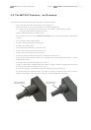
The Laser Shutter Manual Control
The laser shutter manual control features
—
A D-sub 15-pin female plug to connect with the LAS-MC plug of the LAS-BOB break-out box
—
Four LASER 1, 2, 3, 4 switches to open and close each high-speed laser shutter individually
—
A REMOTE switch to set the shutters to remote control via external TTL triggers or ODB de-
vice bus communication (typically controlled by a software like cell^M / cell^R)
—
A mode lock with key to allow authorized and trained personnel to switch from standard USER
MODE to MAINTENANCE (see Chapter 5, Modes of Operation).
—
A red emergency interrupter that close all safety shutters when pressed