17
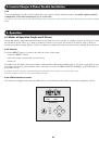
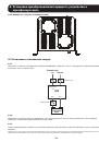
6. Operation
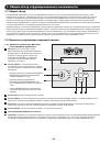
In most display modes, the upper left row of text continuously identifies the current operational mode. Supported modes are
STANDBY, INVERTER, CHARGER and SETTING.
The upper right and entire lower row of text identifies particular measurement values. To scroll between the various
measurement screens, press the UP or DOWN button. The display can be “parked” on a particular value for full-time display
while the inverter is running in that mode.
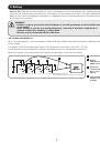
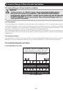
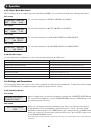
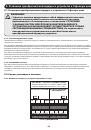
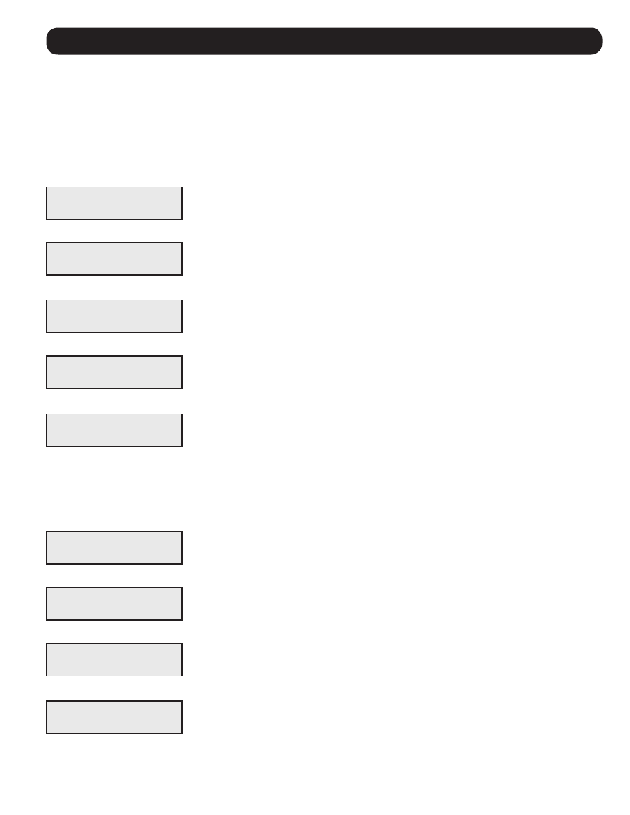
6.1.3 Standby Mode Main Status
1st screen
The BATTERY CAPACITY is displayed by charge percentage
2nd screen
The BATTERY VOLTAGE and CURRENT is displayed.
3rd screen
The INPUT VOLTAGE and CURRENT from the AC or DC power source is displayed in voltage
and amps.
4th screen
The OUTPUT VOLTAGE and FREQUENCY is displayed.
5th screen
The heat-sink and transformer TEMPERATURES are displayed in Celsius.
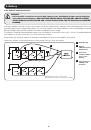
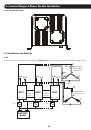
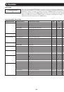
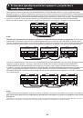
6.1.4 Inverter Mode Main Status
When in Inverter mode, the upper right corner will display the OUTPUT LOAD CAPACITY in VA. The second line will display the
following data values:
1st screen
The second line displays the BATTERY VOLTAGE and CURRENT.
2nd screen
The second line displays the OUTPUT VOLTAGE and FREQUENCY
3rd screen
The second line displays the L1 - LINE (L) LOAD CURRENT and LOAD CAPACITY.
4th screen
The second line displays the L2 - LINE (N) LOAD CURRENT and LOAD CAPACITY.
STANDBY
BAT 100%
STANDBY
BAT 53.2V 0.0A
INVERTING 253VA
BAT 53.2V 0.0A
STANDBY
AC 240.0V 0.0A
INVERTING 253VA
240.0V 50Hz
STANDBY
0.0V 50Hz
INVERTING 253VA
L1
1.0A 253VA
INVERTING 253VA
L2
1.0A 253VA
STANDBY
25.0C 25.0C