20
6. Operation
6.3 Single-Phase Parallel Operation
6.3.1 Enabling Single-Phase Parallel Operation through Parameter Settings
Note: For more information on the Inverter/Charger’s general operation, review sections 6.1 and 6.2.
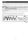
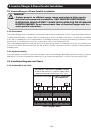
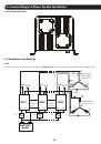
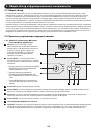
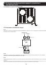
Once the batteries have been configured in series-parallel (see subsection 3.4.3) and the Inverter/Chargers have been
connected through the ASNET and PARALLEL STACKED INVERTER ports (see section 4.4), turn on the power to the first
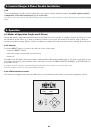
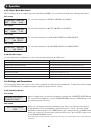
Inverter/Charger. After the first Inverter/Charger has completed booting, the LCD will display the main status screen. From the
main status screen, go to the PARAMETER SELECTION page located in the Setting mode. Once inside the parameter settings,
set the PARALLEL ENABLE value to 1. The first Inverter/Charger will now be configured as master with an ID set to 32.
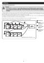
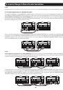
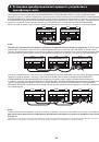
Proceed to power on all other connected Inverter/Chargers to enter standby mode. If the CANbus network established through
the PARALLEL STACKED INVERTERS connections is successful, the master Inverter/Charger will display ID32 in the LCD and
each connected slave Inverter/Charger unit will display a unique ID starting at 33, followed by 34, 35, and so on.
6.3.2 Auto Master Setting
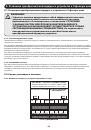
When only one Inverter/Charger is powered on in a parallel system, it will display ‘CAN BUS NO RESPONSE’ on the unit’s
LCD. When another Inverter/Charger turns on through normal CAN BUS operation, the first Inverter/Charger powered will be
the master. If both Inverter/Chargers power at the same time, then the inverter with the smaller ID will become the master.
Because the system already has a master, even if a third inverter ID is smaller than the master, it could only be a slave.
Note: When the master fails or is offline, the slave inverter with the smallest ID will become the master.
6.3.3 Average Output Load
A slave will automatically switch from standby to the output based on a parallel system’s average load. When the total load is
over 1800W, the inverter that is in standby mode with the smallest ID will change to output mode. When the average load is
under 1350W, the inverter that is in output mode with the biggest ID will change to standby mode.