10
UT207A/208A/209A Operating Manual
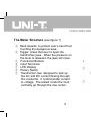
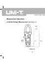
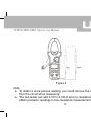
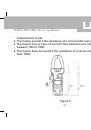
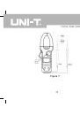
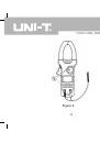
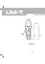
The Meter Structure
(see figure 1)
①
Hand Guards: to protect user’s hand from
touching the dangerous area.
②
Trigger: press the lever to open the
transformer jaws. When the pressure on
the lever is released, the jaws will close.
③
Functional Buttons
④
Input Terminals
⑤
LCD Display
⑥
Rotary Switch
⑦
Transformer Jaw: designed to pick up
the AC and DC current flowing through
the conductor. It could transfer current
to voltage. The tested conductor must
vertically go through the Jaw center.
Figure 1