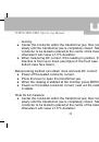
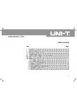
Страница 2 из 48 UT207A/208A/209A Operating Manual Table of Contents Title Overview Unpacking Inspection Safety Information Rules for Safe Operation International Electrical Symbols The Meter Structure Display Symbols Functional Buttons The Effectiveness of Functional Buttons Measurement Operation A. DC/AC Voltage
Страница 3 из 48 UT207A/208A/209A Operating Manual Specifications A. General Specifications B. Environmental Requirements Accuracy Specifications Maintenance A. General Service B. Replacing the Battery 35 35 36 37 43 43 44 2
Страница 4 из 48 UT207A/208A/209A Operating Manual Overview This Operating Manual covers information on safety and cautions. Please read the relevant information carefully and observe all the Warnings and Notes strictly. Warning To avoid electric shock or personal injury, read the “Safety Information” and “Rules
Страница 5 из 48 UT207A/208A/209A Operating Manual Unpacking Inspection Open the package case and take out the Meter. Check the following items carefully to see any missing or damaged part: Item 1 2 3 4 5 Description English Operating Manual Test Lead Point Contact Temperature Probe (Only UT208A) (This included
Страница 6 из 48 UT207A/208A/209A Operating Manual Safety Information This Meter complies with the standards IEC61010: in pollution degree 2, overvoltage category (CAT II 600V, CAT III 300V) and double insulation. CAT II: Local level, appliance, PORTABLE EQUIPMENT etc., with smaller transient overvoltages than CAT
Страница 7 из 48 UT207A/208A/209A Operating Manual Rules for Safe Operation Warning To avoid possible electric shock or personal injury, and to avoid possible damage to the Meter or to the equipment under test, adhere to the following rules: ● Before using the Meter inspect the case. Do not use the Meter if it is
Страница 8 из 48 UT207A/208A/209A Operating Manual ● ● ● ● ● ● ● ● ● ● changeover of range shall be made during measurement is conducted to prevent damage of the Meter. Do not carry out the measurement when the Meter’s back case and battery compartment are not closed to avoid electric shock. Do not input higher
Страница 9 из 48 UT207A/208A/209A Operating Manual electrical specifications replacement parts. ● The internal circuit of the Meter shall not be altered at will to avoid damage of the Meter and any accident. ● Soft cloth and mild detergent should be used to clean the surface of the Meter when servicing. No abrasive
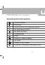
Страница 10 из 48 UT207A/208A/209A Operating Manual International Electrical Symbols Double Insulated Grounding Warning. Refer to the Operating Manual AC (Alternating Current) DC (Direct Current) Continuity Test Diode Deficiency of Built-In Battery AC or DC Danger of High Voltage Conforms to Standards of European
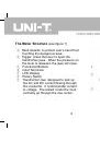
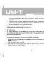
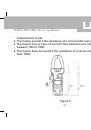
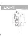
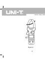
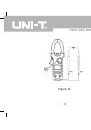
Страница 11 из 48 UT207A/208A/209A Operating Manual The Meter Structure (see figure 1) ① Hand Guards: to protect user’s hand from touching the dangerous area. ② Trigger: press the lever to open the transformer jaws. When the pressure on the lever is released, the jaws will close. ③ Functional Buttons ④ Input
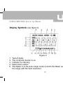
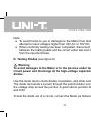
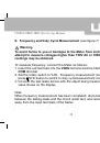
Страница 12 из 48 UT207A/208A/209A Operating Manual Display Symbols (see figure 2) 1. 2. 3. 4. 5. Figure 2 Test of diode The continuity buzzer is on Indicator for zeroing Data hold is active The Meter is in the auto range mode in which the Meter automatically selects the range with the best resolution. 11
Страница 13 из 48 UT207A/208A/209A Operating Manual 6. True RMS indicator 7. Indicator for AC voltage or current 8. Indicates negative reading 9. Indicator for DC voltage 10. The battery is low. Warning: To avoid false readings, which could lead to possible electric shock or personal injury, replace the battery as
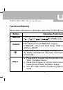
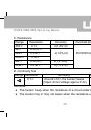
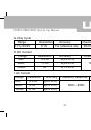
Страница 14 из 48 UT207A/208A/209A Operating Manual Functional Buttons Below table indicated for information about the functional button operations. Button SELECT RANGE HOLD Operation Performed Press SELECT button to select the alternate functions including Ω UT208A only) V , A and .( Range feature: Exit AUTO and
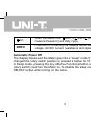
Страница 15 из 48 UT207A/208A/209A Operating Manual Hz% ZERO When the Meter is at %Hz, V and A , press %Hz to measure frequency and duty cycle. Press ZERO to zeroing the display before measuring AC/DC voltage, AC/DC current, resistance and capacitance. Automatic Power Off The display blanks and the Meter goes into a
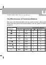
Страница 16 из 48 UT207A/208A/209A Operating Manual The Effectiveness of Functional Buttons Not every functional buttons can be used on every rotary switch positions. Below table describe which functional buttons can be used on which rotary switch positions. Rotary Switch Positions SELECT V ● RANGE ● Functional
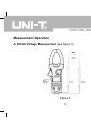
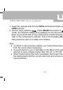
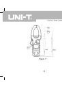
Страница 17 из 48 UT207A/208A/209A Operating Manual Measurement Operation A. DC/AC Voltage Measurement (see figure 3) Figure 3 16
Страница 18 из 48 UT207A/208A/209A Operating Manual Warning To avoid harms to you or damages to the Meter from eletric shock, do not attempt to measure voltages higher than 750V AC or 1000V DC, although readings may be obtained. To measure DC/AC voltages, connect the Meter as follows: 1. Insert the red test lead
Страница 19 из 48 UT207A/208A/209A Operating Manual circuit impedance is less than or equal to 10kΩ, the error is negligible (0.1% or less). ● When DC/AC voltage measurement has been completed, disconnect the connection between the testing leads and the circuit under test and remove testing leads from the input
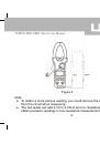
Страница 20 из 48 UT207A/208A/209A Operating Manual Figure 4 Note: ● To obtain a more precise reading, you could remove the objects being tested from the circuit when measuring. ● The test leads can add 0.1Ω to 0.3Ω of error to resistance measurement. To obtain precision readings in low-resistance measurement,
Страница 21 из 48 UT207A/208A/209A Operating Manual input terminals beforehand, press ZERO to automatically subtract the value measured when the testing leads are short-circuited from the reading. ● For high-resistance measurement (>1MΩ), it is normal to take several seconds to obtain a stable reading. ● To avoid
Страница 22 из 48 UT207A/208A/209A Operating Manual measurement mode. 3. The buzzer sounds if the resistance of a circuit under test is less than 10Ω. 4. The buzzer may or may not sound if the resistance of a circuit under test is between 10Ω to 100Ω. 5. The buzzer does not sound if the resistance of a circuit under
Страница 23 из 48 UT207A/208A/209A Operating Manual Note ● To avoid harms to you or damages to the Meter from eletric shock, do not attempt to input voltages higher than 33V AC or 70V DC. ● When continuity testing has been completed, disconnect the connection between the testing leads and the circuit under test and
Страница 24 из 48 UT207A/208A/209A Operating Manual 1. Insert the red test lead into the VΩHz terminal and black test lead into the COM terminal. 2. Set the rotary switch to . Press SELECT to switch to measurement mode. For forward voltage drop readings on any semiconductor component, place the red test lead on the
Страница 26 из 48 UT207A/208A/209A Operating Manual E. Frequency and Duty Cycle Measurement (see figure 7) Warning To avoid harms to you or damages to the Meter from eletric shock, do not attempt to measure voltages higher than 750V AC or 1000V DC, although readings may be obtained. To measure frequency, connect the
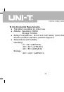
Страница 28 из 48 UT207A/208A/209A Operating Manual F. DC/AC Current Measurement (see figure 8) Warning The operating temperature must be 0℃ ~40℃ when measuring current. To measure current, do the following: 1. Set the rotary switch to 40A ,400A , or 1000A . DC mesaurement mode is a default. Press SELECT to switch
Страница 30 из 48 UT207A/208A/209A Operating Manual zeroing. ● Center the conductor within the transformer jaw, then release the Meter slowly until the transformer jaw is completely closed. Make sure the conductor to be tested is placed at the center of the transformer jaw, otherwise it will cuase ±1.0 % deviation.
Страница 31 из 48 UT207A/208A/209A Operating Manual ● The meter will zero automatically. ● When the measuring current >1A, press Hz button to toggle between AC current and frequency measurement mode. But the frequency readings obtained from this range is only for reference. ● Change to AC: UT207A/208A: Couple AC and
Страница 32 из 48 UT207A/208A/209A Operating Manual G. Temperature Measurement (UT208A only, see figure 9) To measure temperature measurement, connect the Meter as follows: 1. Insert the red temperature probe into the VΩHz terminal and the black temperature probe into the COM terminal. 2. Set the rotary switch to ℃
Страница 34 из 48 UT207A/208A/209A Operating Manual H. Capacitance measurement (UT208A only, see figure 10) To avoid harms to you or damages to the Meter from eletric shock, do not attempt to input voltages higher than 33V AC or 70V DC. To measure capacitance, do the following: 1. Insert the red test lead into the
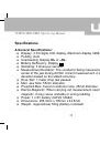
Страница 36 из 48 UT207A/208A/209A Operating Manual Specifications A.General Specifications: ● Display: 3 3/4 digits LCD display, Maximum display 3999. ● Polarity: Auto ● Overloading: Display OL or –OL. ● Battery Deficiency: Display . ● Sampling: 3 times per second. ● Measurement Deviation: The conductor being
Страница 37 из 48 UT207A/208A/209A Operating Manual B. Environmental Requirements ● The Meter is suitable for indoor use. ● Altitude: Operating: 2000m Storage: 10000m ● Safety/ Compliances: IEC 61010 CATII 600V, CATIII 300V over voltage and double insulation standard, pollution degree 2. ● Temperature and humidity:
Страница 38 из 48 UT207A/208A/209A Operating Manual Accurate Specifications Accuracy: ±(a% reading + b digits), guarantee for 1 year. Operating temperature: 23℃±5℃ Relative humidity: ≤80%R.H Temperature coefficient: 0.1×(specified accuracy)/1℃ A. DC Voltage Range Resolution Accuracy 400mV 0.1mV ±(0.8%+3) 4V 0.001mV
Страница 39 из 48 UT207A/208A/209A Operating Manual B. AC Voltage Range Resolution Accuracy Overload protection 400mV 0.1mV ±(1.2%+20) 4V 0.001mV 40V 0.01V ±(1.2%+3) DC1000V/AC750V 400V 0.1V 750V 1V ±(1.2%+5) Remarks: ● Input Impedance: 10MΩ ● Frequency Response: 40Hz~400Hz ● Change to AC: UT207A/208A: Couple AC and
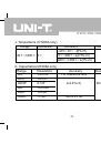
Страница 40 из 48 UT207A/208A/209A Operating Manual C. Resistance Range Resolution 400Ω 0.1Ω 4kΩ 0.001KΩ 40kΩ 0.01KΩ 400kΩ 0.1KΩ 4MΩ 0.001MΩ 40MΩ 0.01MΩ D. Continuity Test Range Resolution 0.1Ω Accuracy ±(1.2%+2) Overload protection ±(1.0%+2) DC1000V/AC750V ±(1.2%+2) ±(1.5%+2) Accuracy Around ≤10Ω,the buzzer beeps.
Страница 41 из 48 UT207A/208A/209A Operating Manual E. Diode Test Range Resolution 1mV Accuracy Overload Protection 0.5V~0.8V DC1000V (Open circuit voltage approx. 1.5V) /AC750V F. Frequency Range Resolution Accuracy 400Hz 0.1Hz 4kHz 0.001kHz 40kHz 0.01kHz 400kHz 0.1kHz ±(0.1%+3) 4MHz 0.001MHz 40MHz 0.01MHz Remarks:
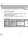
Страница 42 из 48 UT207A/208A/209A Operating Manual G. Duty Cycle Range 0.1%~99.9% H. DC Current Range 40A 400A 1000A Resolution Accuracy 0.1% For reference only Resolution 0.01A 0.1A 1A Accuracy ±(2.0%+5) ±(2.0%+3) ±(1.5%+5) Overload Protection DC1000V/AC750V Overload protection I. AC Current Range Resolution
Страница 43 из 48 UT207A/208A/209A Operating Manual J. Temperature (UT208A only) Range Resolution -40℃~1000℃ 1℃ Accuracy -40℃~0℃: -(8%+5) 0℃~400℃: ±(2.5%+3) 400℃~1000℃: ±(3%+3) K. Capacitance(UT208A only) Range Resolution Accuracy 4nF 0.001nF For reference only 40nF 0.01nF 400nF 0.1nF ±(4.0%+3) 4μF 0.001μF 40μF
Страница 44 из 48 UT207A/208A/209A Operating Manual Maintenance This section provides basic maintenance information including battery replacement instruction. Warning Do not attempt to repair or service your Meter unless you are qualified to do so and have the relevant calibration, performance test, and service
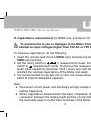
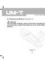
Страница 45 из 48 UT207A/208A/209A Operating Manual B. Replacing the Battery (see figure 11) Warning To avoid false readings, which could lead to possible electric shock or personal injury, replace the battery as soon as the battery indicator “ appears. figure 11 44 ”
Страница 46 из 48 UT207A/208A/209A Operating Manual Make sure the transformer jaw and the tets leads are disconected from the circuit being tested before opening the case bottom. To replace the battery: 1. Turn the Meter off and remove all the connections from the input terminals 2. Turn the Meter’s front case down.