GB
17
reach a temperature of 50°;
• it should not pass through holes or slits used for
discharging the oven flue gases;
• it should not come into contact with pointed parts
or sharp corners;
• it should be easy to inspect along its entire length
in order to be able to check its condition;
• it should be replaced before the date printed on
the actual pipe.
Important: A pressure regulator, in
Important: A pressure regulator, in
Important: A pressure regulator, in
Important: A pressure regulator, in
Important: A pressure regulator, in
compliance with the applicable norm in force,
compliance with the applicable norm in force,
compliance with the applicable norm in force,
compliance with the applicable norm in force,
compliance with the applicable norm in force,
must be inserted when connecting to a liquid
must be inserted when connecting to a liquid
must be inserted when connecting to a liquid
must be inserted when connecting to a liquid
must be inserted when connecting to a liquid
gas supply (in a cylinder).
gas supply (in a cylinder).
gas supply (in a cylinder).
gas supply (in a cylinder).
gas supply (in a cylinder).
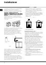
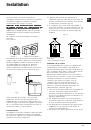
Upon completion of installation, check for leaks from
the gas circuit using a soapy solution (never use a
flame). Make sure that the natural gas pipe is
adequate for a sufficient supply to the appliance
when all the burners are lit.
Adapting to different types of gas (instructions for
the hob)
To adapt the hob to a different type of gas from the
factory-set one (indicated on the rating plate at the
top of the hood or on the packaging), the burner
nozzles should be replaced as follows:
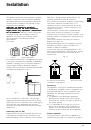
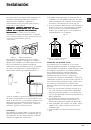
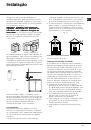
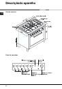
• Remove the hob grids and slide the burners off
their seats.
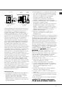
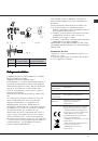
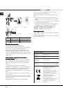
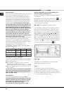
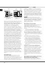
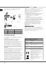
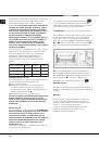
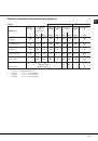
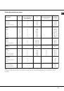
• Unscrew the nozzles (fig. 13), using a 7 mm
socket spanner and replace them with nozzles for
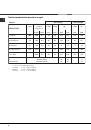
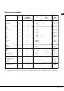
the new type of gas (see table 1 "Burner and
nozzle characteristics").
Reassemble the parts following the above
procedure in the reverse order.
• On completion of this operation, replace the old
rating sticker with one indicating the new type of
gas used. This sticker is available in the "kit of
nozzle".
Adjusting the primary air of the burners
The primary air of the burners does not need to be
adjusted.
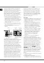
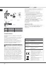
Adjusting the low flame
• Turn the tap to the low flame position;
• Remove the knob and turn the adjusting screw,
situated to the right of the tap (fig. 14) until you
obtain a regular small flame, using a screwdriver
(loosening the screw increases the height of the
flame, tightening decreases it).
N.B.:
N.B.:
N.B.:
N.B.:
N.B.: In the case of liquid gas, the regulation
screw must be screwed in all the way.
• Having obtained the low flame setting required
and with the burner lit, abruptly change the
position of the knob several times from minimum
to maximum and vice versa and check that the
flame does not go out.
• In appliances fitted with the safety device
(thermocouple), should the device fail to work with
the burners set to the low flame setting, increase
the low flame setting of the same on the adjusting
screw.
Once the adjustment has been made, remount the
seals on the by-passes using sealing wax or similar.
Gas oven:
• Open the oven door (to reach the oven burner,
remove the floor);
• loosen the 2 screws which hold the oven burner in
place, remove the burner and replace the nozzles
"N"
"N"
"N"
"N"
"N" with suitable ones for the new type of gas
according to the table on page 12.
• re-assemble all the components, regulate the air
in the burner as well as the minimum flow of the
tap.
Adjusting the low flame
• Open the door and remove the oven floor;
• put the oven knob to position maximum and light
the burner;
• close the door and wait for about 15 minutes;
• put the knob to position 1 (minimum);
• remove the actual knob and regulate the adjusting
screw situated above the thermostat spindle;
• after regulating the low flame as required, with the
burner lit, change from the high to the low flame
position abruptly for a few times and close the
oven door normally, making sure that the burner
does not go out.
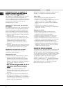
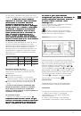
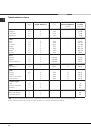
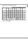
Primary air flow control
The oven burners and grill are fitted with the primary
air control bushing “R” (fig. 15: gas oven burners).
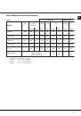
The primary air flow is controlled in an appropriate
way when the flame is stable and even, without
killing the flame when the burner is cold or lighting
the nozzle when the burner is hot. The flow may be
adjusted by loosening the screw “P” and moving the
bushing “R” so that the opening “X
XX
XX” corresponds to
the values in the table below. Once all the
adjustments have been made, fasten the bushing
“R” with the screw “P”.