6
XENYX QX1202USB/QX1002USB User Manual
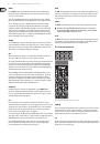
GAIN
Use the
GAIN
control to adjust the input gain. This control should always be
turned fully counterclockwise whenever you connect or disconnect a signal
source to one of the inputs.
The scale has 2 different value ranges: the first value range (+10 to +60 dB)
refers to the MIC input and shows the amplification for the signals fed in there.
The second value range (-10 to +40 dBu) refers to the line input and shows
its sensitivity. The settings for equipment with standard line-level signals
(-10 dBV or +4 dBu) look like this: While the GAIN control is turned all the way
down, connect your equipment. Set the GAIN control to the external devices’
standard output level. If that unit has an output signal level display, it should
show 0 dB during signal peaks. For +4 dBu, turn up GAIN slightly, for -10 dBV a
bit more. Tweaking is done using the CLIP LED.
COMP
Use the COMP knob to adjust the amount of compression effect on the channel.
Compression limits the dynamic range of the audio source, which can help vocals
cut through a mix better, for example. Turn the COMP knob clockwise until the
adjacent LED occasionally lights during speech/singing.
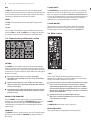
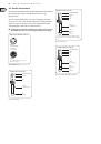
EQ
All mono input channels include a 3-band equalizer. All bands provide boost or
cut of up to 15 dB. In the central position, the equalizer is inactive.
The circuitry of the British EQs is based on the technology used in the best-known
top-of-the-line consoles and providing a warm sound without any unwanted
side effects. The result are extremely musical equalizers which, unlike simple
equalizers, cause no side effects such as phase shifting or bandwidth limitation,
even with extreme gain settings of ±15 dB.
The upper (HIGH) and the lower band (LOW) are shelving filters that increase
or decrease all frequencies above or below their cut-off frequency. The cut-off
frequencies of the upper and lower band are 12 kHz and 80 Hz respectively.
The mid band is configured as a peak filter with a center frequency of 2.5 kHz.
Unlike shelving filters, the peak filter processes a frequency range that extends
upwards and downwards around its middle frequency.
LOW CUT
In addition, the mono channels are equipped with a steep
LOW CUT
filter
designed to eliminate unwanted low-frequency signal components. These can
be noises created by hand-held microphones, subsonic noise or plosive sounds
created by highly sensitive microphones.
FX
FX sends enable you to feed signals via a variable control from one or more
channels and sum these signals to a bus. The bus appears at the console’s FX send
output and can be fed from there to an external effects device. The return from
the effects unit is then brought back into the console on the stereo channels.
Each FX send is mono and features up to +15 dB gain.
As the name suggests, the
FX
sends of the XENYX mixing consoles are intended to
drive effects devices (reverb, delay, etc.) and are therefore configured post-fader.
With XENYX mixing consoles, the channel fader is called LEVEL control.
In the QX1002/1202USB, the FX send is routed directly to the built-in effects
processor. To make sure that the effects processor receives an input signal,
you shouldn’t turn this control all the way to the left (-∞).
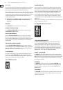
PAN
The
PAN
control determines the position of the channel signal within the stereo
image. This control features a constant-power characteristic, which means the
signal is always maintained at a constant level, irrespective of position in the
stereo panorama.
LEVEL
The
LEVEL
control determines the level of the channel signal in the main mix.
◊
Attention: Since the FX path for the effect processor is connected
post-fader, the LEVEL control has to be turned up in order to get this
channel’s signal to the effects processor!
CLIP
The
CLIP
-LED’s of the mono channels illuminate when the input signal is driven
too high, which could cause distortion. If this happens, use the GAIN control to
reduce the preamp level until the LED does not light anymore.
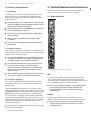
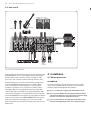
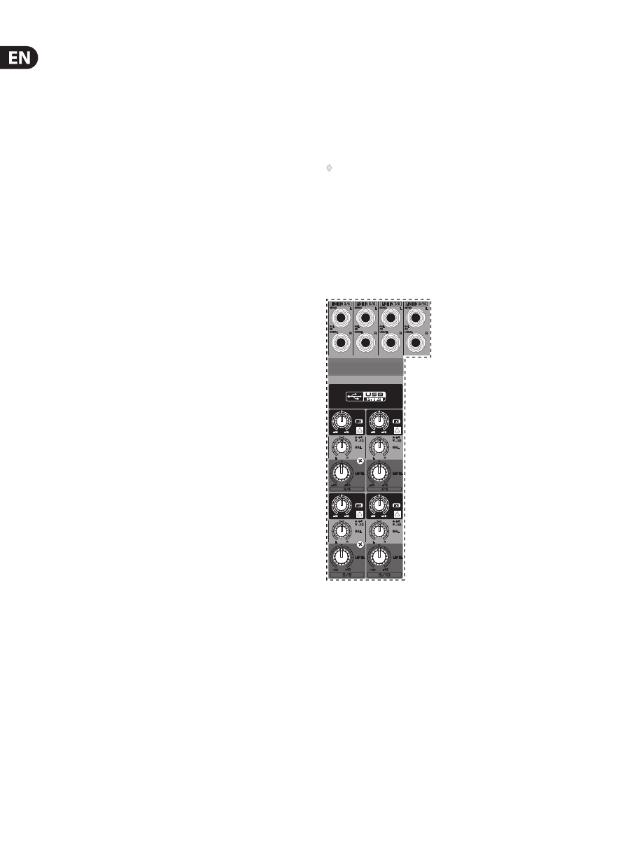
2.2 Stereo channels
Fig. 2.2: Connectors and controls on the stereo channels
LINE IN
Each stereo channel has two balanced line level inputs on ¼" connectors for left
and right channels. If only the connector marked “L” (left) is used, the channel
operates in mono. The stereo channels are designed to handle typical line level
signals. Both inputs will also accept unbalanced connectors.
FX
The FX send of the stereo channels functions similar to that of the mono channels.
However, since the FX send bus is mono, a mono sum is first taken from the stereo
input before it is sent to the FX bus.