7
XENYX QX1202USB/QX1002USB User Manual
BAL
The
BAL
(ANCE) control determines the levels of left and right input signals
relative to each other before both signals are then routed to the main stereo mix
bus. If a channel is operated in mono via the left line input, this control has the
same function as the PAN control used in the mono channels.
LEVEL
The
LEVEL
control determines the volume of the channel being sent to the
main mix.
+4/-10
The stereo inputs of the XENYX have an input sensitivity switch which selects
between
+4 dBu
and -10 dBV. At
-10 dBV
(home-recording level), the input is
more sensitive (requires less level to drive it) than at +4 dBu (studio level).
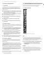
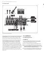
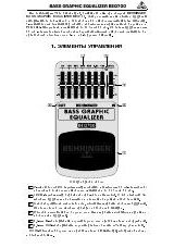
2.3 Connector array of the main section
Fig. 2.3: Connectors of the main section
FX SEND
The
FX SEND
connector outputs the signal you picked up from the individual
channels using the FX controls. You can connect this to the input of an external
effects device in order to process the FX bus’ master signal. Once an effects mix is
created, the processed signal can then be routed from the effects device outputs
back into a stereo input.
◊
If the connected effects processor receives no input signal,
the FX SEND control is probably too low. This also goes for the built-in
effects processor.
◊
Adjust your external effects processor to 100% wet (effects signal
only), because the effects signal is added to the main mix along with
the “dry” channel signals.
◊
In this instance, the FX control of the channel being used as an effects
return should be turned fully counterclockwise, otherwise feedback
problems can occur!
PHONES/CTRL ROOM OUT
The stereo
PHONES
connector (at the top of the connector panel) is where
headphones are connected. The balanced
CTRL ROOM OUT
connectors carry
the summed effects and main mix signals. The PHONES/CONTROL ROOM
control in the main section adjusts the level of both headphones and main
monitor outputs.
MAIN OUT
The
MAIN OUT
connectors are balanced mono connectors. The main mix signal
appears here at a level of 0 dBu. The
MAIN MIX
fader adjusts the volume of
these outputs.
2-TRACK INPUT
The
2-TRACK INPUTs
are used to bring an external signal source (e.g. CD player,
tape deck, etc.) into the console. They can also be used as a standard stereo line
input, so the output of a second XENYX or BEHRINGER ULTRALINK PRO MX882 can
be connected. Alternatively the line or tape output of a hi-fi amplifier with source
selection switch could also be hooked up here, allowing you to easily listen to
additional sources (e.g. CD player, MP3 player, sound card etc.).
2-TRACK OUTPUT
These connections are laid out as RCA connectors and are wired parallel to
MAIN OUT. Connect the inputs of a computer sound card or a recorder here.
The output signal level is set up using the highly accurate MAIN MIX fader.
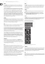
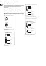
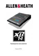
2.4 Main section
CLIP
SIG
Fig. 2.4: Control elements of the main section
+48 V
The red “+48 V” LED lights up when the phantom power is turned on.
Phantom power is required to operate condenser microphones and is activated
using the +48 V switch located above the +48 V LED.
◊
Connect microphones before you switch on the phantom power supply.
Please do not connect microphones to the mixer (or the stagebox/
wallbox) while the phantom power supply is switched on. In addition,
the monitor/PA loud speakers should be muted before you activate the
phantom power supply. After switching on, wait approx. one minute to
allow for system stabilization.
◊
Caution! You must never use unbalanced XLR connectors
(PIN 1 and 3 connected) on the MIC input connectors if you want to
use the phantom power supply.
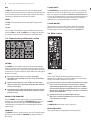
POWER
The
POWER LED
indicates that the console is powered on.
LEVEL INDICATOR
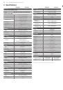
The 4-segment display accurately displays the relevant signal level.