10
XENYX QX2442USB/QX2222USB/QX1832USB/QX1622USB User Manual
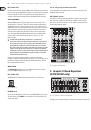
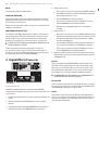
Monitor mix with effect
In this instance, your effects device should be set up as follows: the AUX SEND 2
jack should be connected to the L/Mono input of your effects device, with its
outputs coming back into the STEREO AUX RETURN 1 jacks.
Connect the AUX SEND 1 jack output to the amplifier of your monitor system.
The AUX SEND 1 master control determines the overall volume of the
monitor mix.
Using the STEREO AUX RETURN (TO AUX SEND) control, the effect signal can now
be blended into the monitor mix.
You can easily use the headphones distribution amplifier BEHRINGER POWERPLAY
PRO HA4700/HA8000 to provide four (HA8000: eight) stereo headphone mixes for
your studio.
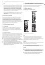
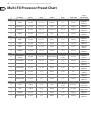
The following table shows which jacks on the console can be used for
this purpose.
External effects device
receives signal from...
External effects device
routes signal back to...
The effect signal reaches the
monitor mix via…
QX1622USB
AUX SEND 2
STEREO AUX RETURN 1
connectors
STEREO AUX RETURN 1
(TO AUX SEND 1) control
QX1832USB
AUX SEND 1
STEREO AUX RETURN 2
connectors
MONITOR switch of the
FX/AUX 2 RET
QX2222USB
AUX SEND 2
STEREO AUX RETURN
connectors 1 or 2
STEREO AUX RETURN 1
(TO AUX SEND 1) control
QX2442USB
AUX SEND 2
STEREO AUX RETURN 1
connectors
STEREO AUX RETURN 1
(TO AUX SEND 1) control
optional:
AUX SEND 1
STEREO AUX RETURN 2
connectors
STEREO AUX RETURN 2
(TO AUX SEND 2) control
Tab. 2.1: Connectors and controls for monitor mix with effect
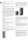
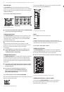
STEREO AUX RETURN FX
On consoles QX1622USB and QX1832USB this is the
STEREO AUX RETURN 2
,
on consoles QX2222USB and QX2442USB this is the
STEREO AUX RETURN 3
.
Use the STEREO AUX RETURN FX control to determine the level of the signal
routed from the AUX RETURN FX jacks to the main mix. If nothing is connected to
these jacks, the output of the built-in effects module will appear.
MAIN MIX / TO SUBS
This switch routes the signal fed in via the STEREO AUX RETURN FX jacks either to
the main mix (not pressed) or to the submix (pressed).
On the QX2442USB you can select which subgroup the signal is assigned to
(switches 1-2 / 3-4, to the right of MAIN MIX / TO SUBS).
SOLO RETURNS
Additionally, this model allows you to route the aux returns together to the solo
bus and the PFL bus. The LED lights up when Solo is on.
STEREO AUX RETURN 4 (QX2442USB only)
This control behaves the same way as the other stereo aux returns. Additionally,
it provides for a simple monitor path using the switch PHONES/CTRL ROOM ONLY.
PHONES/CTRL ROOM ONLY
Use this switch to route the signal appearing at the AUX RETURN 4 jacks to the
control room and headphones outputs.
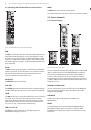
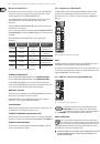
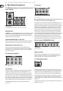
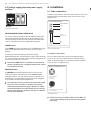
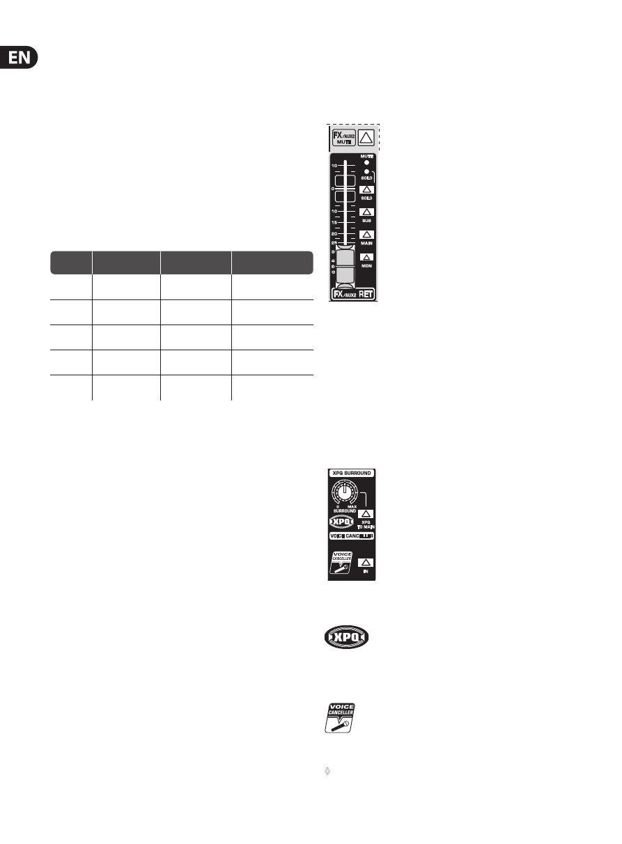
2.3.6 Supplement to QX1832USB
The QX1832USB has a stereo fader for the AUX RETURN FX and offers a variety
of routing options: MUTE disables the effect return (but not PFL of course!),
SOLO routes it to the Solo or PFL busses, SUB to the subgroups and MAIN to the
main mix.
QX1832USB
Fig. 2.13: The FX/AUX 2 return fader of the QX1832USB
MON
The MON switch routes the signals appearing at the AUX RETURN 2 jacks to the
monitor path, along with the monitor signals from the channels.
If you wish to route the effect signal to the monitor mix, you can also switch aux
1 to pre-fader, drive the effect device from the aux 1 output and return the effect
signal via AUX RETURN 2 to the monitor signal.
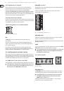
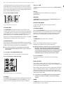
2.3.7 XPQ Surround function (QX1832USB only)
QX1832USB
Fig. 2.14: Control elements of the surround function
The XPQ surround function can be enabled/disabled with the
XPQ TO MAIN
switch. This is a built-in effect that widens the
stereo width, thus making the sound more lively and transparent.
Use the
SURROUND
control to determine the intensity of this effect.
VOICE CANCELLER
Here, you have a filter circuitry that lets you almost entirely remove
the vocal portion of a recording. The filter is constructed in such a way
that voice frequencies are targeted without majorly affecting the rest
of the signal. Additionally, the filter seizes only the middle of the stereo image,
exactly there where the vocals are typically located.
◊
Connect the signal sources you wish to process using the Voice Canceller
to the 2-Track Input connectors. The Voice Canceller circuitry is not
available for other inputs.