11
XENYX QX2442USB/QX2222USB/QX1832USB/QX1622USB User Manual
Possible applications for the Voice Canceller are obvious: you can very simply
stage background music for Karaoke events. Of course, you can also do this at
home or at your rehearsal room before you hit the stage. Singers with their own
band can practice singing difficult parts using a complete playback from a tape
player or a CD, thus minimizing rehearsal time.
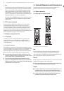
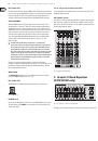
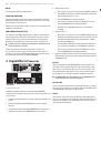
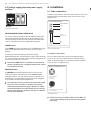
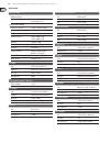
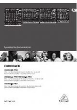
2.3.8 2-Track/USB In and Out
QX2442USB
Fig. 2.15: 2-track connectors and lamp socket
2-TRACK INPUT
The
2-TRACK INPUT
jacks (RCA) are designed to accept a 2-track recorder
(e.g. DAT recorder), or they can be used as stereo line input. The output signal of
a second XENYX can also be connected here. If you connect the output of a hi-fi
amplifier (with a source selection switch) to the 2-TRACK INPUT, you can easily
listen to additional sources (e.g. MP3 player, MD player, sound card, etc.).
Using the voice canceller function (QX1832USB only), you can process all signals
being brought into your mixing console via these connectors.
2-TRACK OUTPUT
These connectors are wired in parallel to the MAIN OUT and carry the main mix
signal (unbalanced). Connect this to the inputs of your recording device. The final
output level can be adjusted via the high-precision MAIN MIX fader.
◊
If you connect a compressor or a noise gate post 2-track output,
the main mix fader will probably not be able to create a satisfactory
fade-out effect.
2.3.9 Lamp socket (QX2442USB only)
Use this BNC socket to connect a gooseneck lamp (12 V DC, max. 0.5 A).
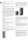
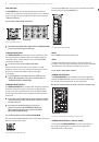
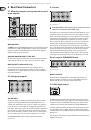
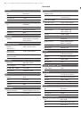
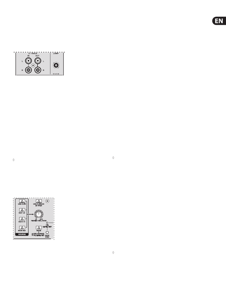
2.3.10 Level meter and monitoring
QX2442USB
Fig. 2.16: Control room and phones sections of the QX2442USB
2-TR/USB
The
2-TR/USB
switch routes the signal from the 2-TRACK and USB inputs to the
level meter, the CONTROL ROOM OUT outputs and the PHONES jack—this is a
simple way to check recorded signals via monitor speakers or headphones.
SUB 1-2 or SUB
The
SUB 1-2
switch routes subgroup 1-2 to the level meter, CONTROL ROOM OUT
and phones.
SUB 3-4
The
SUB 3-4
switch performs a similar function for subgroup 3-4
(QX2442USB only).
MAIN MIX
The
MAIN MIX
switch sends the main mix to the CONTROL ROOM OUT and the
PHONES output as well as to the level meter.
PHONES/CTRL ROOM
Use this control to adjust the control room output level and the
headphones volume.
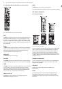
2-TR/USB TO MAIN
When the
2-TR/USB TO MAIN
switch is depressed, the 2-track input is routed to
the main mix and thus serves as an additional input. You can also connect MIDI
instruments or other signals here that do not require any further processing.
At the same time, this switch disables the main mix to tape output link.
POWER
The
POWER LED
indicates that the device is switched on.
+48 V
The red “+48 V” LED lights up when phantom power is switched on.
Phantom power is required to operate condenser microphones.
◊
While phantom power is switched on, do not connect or disconnect
microphones on the mixer (or the stagebox/wallbox). Connect any
microphones before switching on phantom power. Additionally,
monitor/PA speakers should be muted before you activate the phantom
power supply. After switching on, wait approx. one minute before
adjusting the input gain so that the system has time to stabilize.
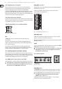
2.3.11 Level Meter
The high-precision level meters always give you an accurate display of
signal level.
LEVEL SETTING:
When recording to digital recorders, the recorder’s meter should not go into
overload. This is because, unlike analog recordings, it takes only slightly excessive
levels to create unpleasant digital distortion.
When recording to analog, the VU meters of the recording machine should reach
approx. +3 dB with low-frequency signals (e.g. kick drum). Due to their inertia,
VU meters tend to display too low a signal level at frequencies above 1 kHz.
You should only drive instruments such as a Hi-Hat as far as -10 dB. Snare drums
should be driven to approx. 0 dB.
◊
The peak meters of your XENYX display level almost independent of
frequency. A recording level of 0 dB is recommended for all types
of signal.
MODE
The
MODE
switch determines whether the channels’ SOLO switch operates as PFL
(Pre Fader Listen) or as solo (Solo In Place).