12
eN
english
!
The appliance must be installed by a qualified person
in compliance with the instructions provided.
!
Wear gloves when carrying out installation and
maintenance operations.
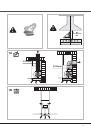
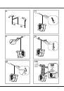
aIr VeNT
(for ducting versions)
!
Prepare the hole and the air vent duct (150 mm dia-
meter).
!
Use a duct of the minimum indispensible length.
!
Use a duct with as few elbows as possible (maximum
elbow angle: 90°).
!
Avoid drastic changes in the duct cross-section.
!
Use a duct with an as smooth as possible inside.
!
The duct must be made of certified material.
!
Do not connect the hood to smoke exhaust ducts
for the products of combustion (boilers, fireplaces,
stoves, etc).
!
For the air vents comply with the provisions laid down
by the competent authorities.
In addition, the air must not be evacuated through a
hole in the wall unless specifically intended for this
purpose.
!
Fit air intakes in the room to prevent the hood from
creating a negative pressure in the room (which must
not exceed 0.04 mbar); if the hood is used at the
same time as non-electrical equipment (gas-, oil- and
charcoal-fired stoves, etc.) the exhaust gas may be
sucked in by the heat source.
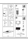
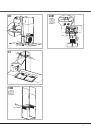
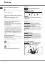
FIlTerING or dUcTING VerSIoN ?
The hood may be in filtering or in ducting version. Deci
-
de from the outset which type is to be installed.
For better efficiency, we recommend installing the hood
in the ducting version (if possible).
ducting version
The hood purifies the air and evacuates it to the outside
through an exhaust duct (diameter 150 mm).
Filtering version
The hood purifies the air and recycles the clean air
back into the room.
For this version, the following are required:
Purchase the recirculation kit
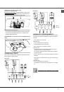
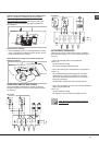
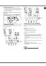
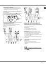
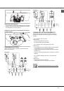
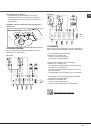
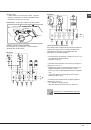
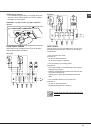
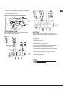
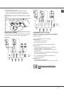
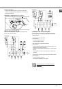
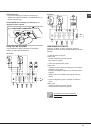
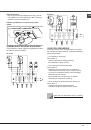
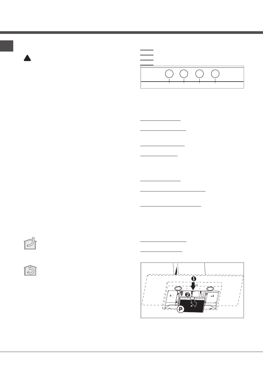
coNTrolS
Key a:
light switch.
Key B:
first speed motor ON/OFF switch.
Key c:
second speed switch.
Key d:
third speed switch.
A
B
C
D
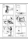
MaINTeNaNce
!
Before cleaning or maintenance cut the power.
cleaning the hood
WHEN TO CLEAN IT: clean it at least every 2 months
to prevent the risk of fire.
EXTERNAL CLEANING: use a cloth moistened in luke-
warm water and neutral detergent (for painted hoods);
use specific products for steel, copper or brass hoods.
INTERNAL CLEANING: use a cloth (or brush) soaked
in denatured ethyl alcohol.
WHAT NOT TO DO: do not use abrasive or corrosi-
ve products (e.g. metal sponges, brushes, too hard
brushes, very aggressive detergents, etc.)
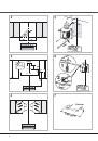
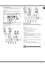
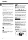
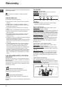
Cleaning the grease filters
WHEN TO CLEAN IT: clean it at least every 2 months to
prevent the risk of fire.
HOW TO REMOVE THE FILTERS: push the catch near
the handle towards the rear of the hood and pull the
filter downwards
HOW TO CLEAN THE FILTERS: hand wash or in the
dishwasher using a neutral detergent. If washing in the
dishwasher, possible discoloration of the filters does not
in any way compromise their functioning.
Replacing the charcoal filter (P)
(for filtering version only)
WHEN TO REPLACE IT: replace it at least every 6
months.
HOW TO REMOVE IT: push the catch inwards and
remove the charcoal filter from its seat.