Инструкция для BOSCH HBG73B550 Edelstahl Einbaubackofen, HBR33B550 Edelstahl Einbaubackofen, HBG78B750 Edelstahl Einbaubackofen, HBG30B550 Edelstahl Einbaubackofen, HBL33B550 Edelstahl Einbaubackofen

de
Ø
Montageanleitung
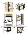
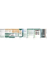
Möbel vorbereiten -Bild 1
■
Nur ein fachgerechter Einbau nach dieser Montageanweisung
garantiert einen sicheren Gebrauch.Bei Schäden durch fal-
schen Einbau haftet der Monteur.
■
Einbaumöbel müssen bis 90 °C temeperaturbeständig sein,
angrenzende Möbelfronten bis 70 °C.
■
Alle Ausschnittarbeiten an Möbel und Arbeitsplatte vor dem
Einsetzen der Geräte durchführen. Späne entfernen, dieFunk-
tion von elektrischen Bauteilen kann beeinträchtigt werden.
■
Vorsicht beim Einbau! Teile, die während der Montage
zugänglich sind, können scharfkantig sein. Zur Vermeidung
von Schnittverletzungen Schutzhandschuhe tragen
■
Die Geräte-Anschlussdose muss im Bereich der schraffierten
Fläche B oder außerhalb des Einbauraumes liegen.
■
Zwischen Gerät und angrenzenden Möbelfronten ist ein Lufts-
palt von 5 mm erforderlich.
■
Nicht befestigte Möbel mit einem handelsüblichen Winkel C
an der Wand befestigen.
Gerät unter Arbeitsplatte - Bild 1
Der Zwischenboden des Umbauschrankes benötigt einen Lüf-
tungsausschnitt.
Arbeitsplatte auf Einbaumöbel befestigen.
Wird der Einbau-Backofen unter einem Kochfeld eingebaut,
beachten Sie die Montageanweisung des Kochfeldes.
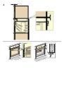
Gerät im Hochschrank - Bild 2
Der Einbau des Gerätes ist auch im Hochschrank möglich.
Zur Belüftung des Backofens müssen die Zwischnböden einen
Spalt von ca. 20 mm zur Anstellwand aufweisen.
Gerät nur so hoch einbauen, dass Backbleche problemlos ent-
nommen werden können.
Eckeinbau - Bild 3
Damit die Gerätetür geöffnet werden kann, beim Eckeinbau
Maße D berücksichtigen. Das Maß E ist abhängig von der Dicke
der Möbelfront unter dem Griff.
Gerät anschließen
Nur ein konzessionierter Fachmann darf das Gerät anschließen.
Es gelten die Bestimmungen des regionalen Elektrizitätsversor-
gers und des Landes.
Bei allen Montagearbeiten muss das Gerät spannungslos sein.
Das Gerät entspricht der Schutzklasse 1 und darf nur mit
Schutzleiter-Anschluss betrieben werden.
Netzanschlussleitung: Typ H05 VV-F oder höherwertig. Die gelb-
grüne Ader für den Schutzleiter-Anschluss muss geräteseitig
10 mm länger sein, als die anderen Adern.
In der Installation muss ein allpoliger Trennschalter mit minde-
stens 3 mm Kontaktöffnung vorhanden sein, oder ds Gerät wird
über einen Stecker mit Schutzkontakt-System angeschlossen.
Dieser muss nach dem Einbau zugänglich sein.
Der Berührungsschutz muss durch den Einbau gewährleistet
sein.
Phase- und Neutral- (“Null-“) Leiter in der Anschlussdose identifi-
zieren. Bei Falschanschluss kann das Gerät beschädigt werden.
Nur nach Anschlussbild anschließen.Spannung siehe Typen-
schild.
Das Gerät zum Anschließen vor dem Möbel abstellen. Das
Anschlusskabel muss entsprechend lang sein.
Einbaugerät befestigen - Bild 4
■
Bei Backwagengeräten den Backwagen herausnehmen.
■
Gerät ganz einschieben und mittig ausrichten.
■
Anschlusskabel nicht knicken.
■
Gerät mit Schrauben(4x25) befestigen.
■
Der Spalt zwischen Arbeitsplatte und Gerät darf nicht durch
zusätzliche Leisten verschlossen werden.
Ausbau
Gerät spannungslos machen. Befestigungsschrauben lösen.
Gerät leicht anheben und ganz herausziehen.
en
Ú
Installation instructions
Preparing the units - Fig. 1
■
The safe operation of this appliance can only be guaranteed if
it has been installed to a professional standard in accordance
with these installation instructions. The installer is liable for
damage incurred as a result of incorrect installation.
■
Fitted units must be heat-resistant up to 90 °C, and
neighbouring unit fronts up to 70 °C.
■
Cut-out work on the units and worktop should be performed
before fitting the appliances. Remove any shavings or the
function of the electrical components may be impaired.
■
Caution during installation. Parts that are accessible during
installation may have sharp edges. Wear protective gloves to
prevent cuts
■
The power socket for the appliance must either be located in
the hatched area B or else away from the installation space.
■
A gap of 5 mm is required between the appliance and
surrounding unit fronts.
■
Secure freestanding units to the wall using a standard bracket
C.
Appliance under the worktop - Fig. 1
There must be a ventilation cut-out made in the intermediate
floor of the surround unit.
Secure the worktop to the fitted units.
If a fitted oven is to be built in under a hob, pay attention to the
hob installation instructions.
Appliance in a tall unit - Fig. 2
The appliance may also be installed in a tall unit.
There must be a gap between the intermediate floors and the
mounting wall of approx. 20 mm in order to provide ventilation
to the oven.
Only fit the appliance at a height where removing baking trays
does not present a problem.
Corner installation Fig. 3
To ensure that the appliance door can be opened in the case of
corner installation, take account of dimension D. Dimension E is
dependent on the thickness of the unit front under the handle.
Connecting the appliance to the power supply
Only allow a licenced professional to connect the appliance.
National regulations apply as well as those of the local electricity
supplier.
The appliance must be disconnected from the power supply for
all installation work.
The appliance corresponds to protection class I and may only
be operated with a protective earth connection.
Power cord: Type H05 VVF or higher rated. The yellow/green
wire for the PE connection must be 10 mm longer than the other
wires on the appliance side.
During installation, an all-pole isolating switch with a contact gap
of at least 3 mm must be present, or the appliance must be
connected via a three-pin earthed plug. This must be accessible
after installation.
Contact protection must be ensured by the installation.
Identify the phase and neutral conductors in the socket.
Incorrect connection may cause damage to the appliance.
Only connect as per the connection diagram. See the rating
plate for the voltage.
Position the appliance in front of the units in readiness for
connection. The connecting cable must be sufficiently long.
Securing the appliance Fig. 4
■
Fully insert the appliance and centre it.
■
Screw the appliance into place.
■
The gap between the worktop and the appliance must not be
closed by additional battens.
Removal
Disconnect the appliance from the power supply. Undo the
securing screws. Raise the appliance slightly and pull it out
completely.


Инструкции и руководства похожие на BOSCH HBG73B550 Edelstahl Einbaubackofen, HBR33B550 Edelstahl Einbaubackofen, HBG78B750 Edelstahl Einbaubackofen, HBG30B550 Edelstahl Einbaubackofen, HBL33B550 Edelstahl Einbaubackofen


Другие инструкции и руководства из категории Кухня


