GB
13
INSTRUCTIONS FOR THE INSTALLER
ImPORTANT NOTICE:
THE OPERATIONS INDICATED BELOW mUST BE FOLLOWED BY QUALIFIED PERSONNEL EXCLUSIvELY,
IN CONFORmITY WITH THE REGULATIONS IN FORCE.
THE mANUFACTURING FIRm REFUSES ALLRESPONSIBILITYFOR DAmAGES TO PEOPLE, ANImALS OR
THINGS, RESULTING FROm THE FAILURE TO COmPLY WITH SUCH PROvISIONS.
INSTALLATION
•
INSTALLATION ROOm
This appliance is not provided with a device for exhausting the products of combustion.
Regarding room ventilation rules where appliance is installed make reference to the legislation, in conformity with
the local regulations.
•
FOR THE U.K. ONLY
The room containing this hotplate should have an air supply in accordance with BS 5440: Part 2:1989.
•
All rooms require an openable window, or equivalent and some rooms will require a permanent vent a well.
•
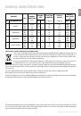
For room volumes up to 5m
3
an air vent of 100cm
2
is required.
•
For room volumes between 5m
3
and 10m
3
an air vent of 50cm
2
is required.
•
If the room is greater than 5m
3
and has a door that opens directly to the outside, then no air vent is required.
If there are other fuel burning appliances in the same room BS 5440: Part 2:1989 should be consulted to determine
the air vent requirements
•
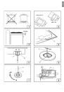
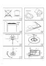
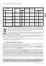
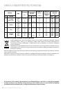
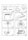
INSTALLING THE TOP
The appliance is designed to be embedded into heat-resistant pieces of furniture.
The walls of the pieces of furniture must resist a temperature at least a 65°C temperature.
The gas hobs are equipped with type Y degree p r o t e c t i o n a g a i n s t o v e r h e a t i n g . T h e r e f o r e , the
appliance can be installed next to cabinets, provided the height of the cabinet doses not exceed that of the hob.
T h e e q u i p m e n t m u s t n o t b e i n s t a l l e d n e a r inflammable materials, such as curtains, cloths, etc.
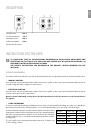
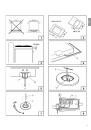
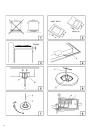
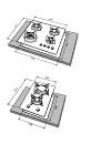
Make a hole in the top of the piece of furniture, with the dimensions (see fig.2), at a distance of at least 50 mm from
the appliance border to the adjacent walls.
Any possible wall unit over the cook-top must be placed at a distance of at least 760 mm from the top.
It is advisable to isolate the appliance from the piece of furniture below with a separator, leaving a depression space
of at least 10 mm (fig. 3).
•
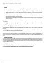
FASTENING THE TOP
Every cook-top is equipped with a special washer having.
This must be placed under the edge of the box unit, as close as possible to the edge itself (fig.4). Introduce and place
the cook-top in the hole made in the piece of furniture, then block it with the screws of the fastening hooks C (fig. 5).
•
GAS CONNECTION
Make sure that the appliance is adjusted for the gas type available (see the label under the appliance). Follow the
instructions indicated in the chapter “gas transformations and adjustments” for the possible adaptation to different
gases. The appliance must be connected to the gas system by means of stiff metal pipes or flexible steel pipes having
continuous walls, in compliance with the regulations in force.
Gas enters the appliance through a cylindrical threaded male gas union (1/2”).
The connection must not stress the gas ramp.
Once the installation is over, check the connection seal with a soapy solution.
INSTRUCTIONS FOR THE INSTALLER