14
INSTRUCTIONS FOR THE INSTALLER
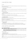
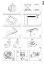
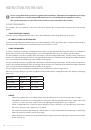
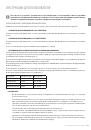
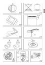
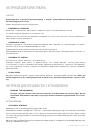
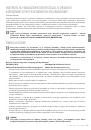
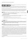
It is advisable to isolate the appliance from the piece of furniture below with a separator, leaving a depression space
of at least 10 mm (fi g. 4).
If the hob is going to be installed on the top of an oven, precautions must be taken to guarantee an installation in
accordance with current accident prevention standards. Pay particular attention to the position of the electric cable
and gas pipe: they must not touch any hot parts of the oven.
Moreover, if the hob is going to be installed on the top of a built in oven without forced cooling ventilation, proper
air vents must be installed to guarantee an adequate ventilation, with the lower air entering with a cross section of at
least 200cm
2
, and the higher air exiting with a cross section of at least 60 cm
2
.
•
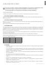
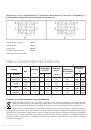
FASTENING THE TOP
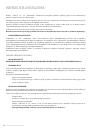
Every cook-top is equipped with a special washer. A set of hooks is also supplied for mounting the cook-top.
For the installation proceed as follows:
•
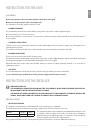
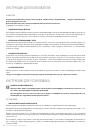
Remove the racks and burners from the top.
•
Turn the appliance upside down and lay the washer S along the external border (fi g. 5).
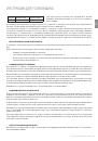
•
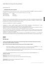
Introduce and place the cook-top in the hole made in the piece of furniture, then block it with the V screws
of the fastening hooks G (fi g.6).
• INSTALLATION
ROOM
This appliance is not provided with a device for exhausting the products of combustion.
Regarding room ventilation rules where appliance is installed make reference to the legislation, in conformity with
the local regulations.
•
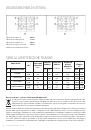
FOR THE U.K. ONLY
The room containing this hotplate should have an air supply in accordance with BS 5440: Part 2: 1989.
•
All rooms require an openable window, or equivalent and some rooms will require a permanent vent a well.
•
For room volumes up to 5m
3
an air vent of 100cm
2
is required.
•
For room volumes between 5m
3
and 10m
3
an air vent of 50 cm
2
is required.
•
If the room is greater than 5m
3
and has a door that opens directly to the outside, then no air vent is required.
If there are other fuel burning appliances in the same room BS 5440: Part 2:1989 should be consulted to determine
the air vent requirements.
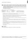
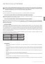
• GAS
CONNECTION
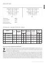
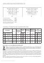
Make sure that the appliance is adjusted for the gas type available (see the label under the appliance). Follow the
instructions indicated in the chapter “gas transformations and adjustments” for the possible adaptation to diff erent
gases.
The appliance must be connected to the gas system by means of stiff metal pipes or fl exible steel pipes having
continuous walls, in compliance with the regulations in force.
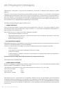
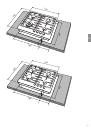
Some models are equipped with both cylindrical A and conical B connectors for gas supply (fi g. 7). Please select the
type which is correct for the supply concerned.
The connection must not stress the gas ramp.
Once the installation is over, check the connection seal with a soapy solution.
• ELECTRIC
CONNECTION
The connection to the electric grid must be carried out by qualifi ed personnel and in conformity with the regulations
in force.
The voltage of the electric system must correspond to the value indicated in the label under the appliance. Make
sure that the electric system is provided with an eff ective ground connction in compliance with the regulations and
provisions of the law. Grounding is compulsory.
INSTRUCTIONS FOR THE INSTALLER