de
Ø
M ontageanleitung
Das müssen Sie beachten
Elektrischer Anschluss:
nur durch konzessionierten
Fachmann. Bei Falschanschluss erlischt die Garantie.
Einbau:
nur fachgerecht, bei Schäden haftet der Monteur.
Anschlussart:
das Gerät entspricht der Schutzklasse I und darf
nur in Verbindung mit Schutzleiteranschluss betrieben werden.
Installation:
in der Installation muss ein allpoliger Trennschalter
mit 3 mm Kontaktöffnung vorhanden sein.
Unterbau:
keine Kühlgeräte, Geschirrspüler, unbelüftete
Backöfen, Waschmaschinen unterbauen.
Zwischenboden:
wenn die Kochfeldunterseite berührbar ist,
muss ein Zwischenboden montiert werden.
Fragen Sie im Fachhandel nach einen Zwischenboden als
Zubehör.
Wenn Sie einen eigenen Zwischenboden verwenden, muss der
Mindestabstand zum Netzanschluss des Gerätes 10 mm
betragen.
Arbeitsplatte:
eben, waagrecht, stabil. Wird ein belüfteter Back-
ofen der gleichen Marke in einem 600 mm hohen Unterbau-
schrank eingebaut, muss die Arbeitsplatte mindestens 40 mm
dick sein.
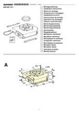
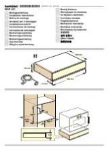
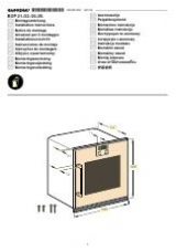
Möbel vorbereiten - Bild 1
Einbaumöbel:
mindestens 90°C temperaturbeständig.
Ausschnitt:
Mindestabstand zu seitlichen Wänden: 70 mm.
Nach Ausschnittarbeiten Späne entfernen.
Schnittflächen:
hitzebeständig versiegeln.
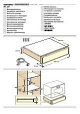
Kochfeld anschließen und einsetzen - Bild 2
Vor Geräteanschluss Hausinstallation überprüfen.
A: Gerät mit 3-adriger Anschlussleitung:
Farbcodierung der
Netzanschlussleitung: grün-gelb = Schutzleiter
<
, blau = (Null)
Neutral-Leiter, braun = Phase (Ausenleiter).
Auf geeignete Absicherung der Hausinatallation achten. Im
Bedarfsfall durch Leitung für mehrphasigen Anschluss
ersetzten. Bei Austauch der Leitung siehe
B:
B: Gerät ohne Anschlussleitung:
nur nach Anschlussbild
anschließen. Bei Bedarf beiliegende Kupferbrücken montieren.
Netzanschlussleitung: Typ H05 VV-F oder höherwertig. Die gelb-
grüne Ader für den Schutzleiter-Anschluss muss geräteseitig
10 mm länger sein, als die anderen Adern.
C: Gerät mit vormontierter5-/6-adriger Anschlussleitung:
nur
ein geschulter Kundendienst-Techniker darf die Anschlusslei-
tung austauschen.
Einsetzen:
Anschlussleitung nicht einklemmen, nicht über
scharfe Kanten führen. Bei untergebautem Backofen Leitung an
den hinteren Ecken des Backofens zur Anschlussdose führen.
Hinweis:
erscheint im Display des Gerätes
—…‹‹
ist es falsch
angeschlossen. Gerät vom Netz trennen, Anschluss überprüfen.
Geflieste Arbeitsplatten:
Fliesenfugen mit Silikonkautschuk
abdichten.
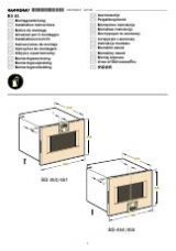
Haltefedern montieren - Bild 3
Gerät mit mindestens 4 Haltefedern montieren.
Kochfeld-Ausbau:
Das Gerät spannungslos machen. Die
Haltefedern lösen. Kochfeld von unten herausdrücken.
en
Ú
I nstallation instructions
The following must be noted
Electrical connection:
To be carried out only by a licensed
expert. Incorrect connection will invalidate the warranty.
Installation:
To be carried out only by a professional. The fitter
is liable for any damage.
Connection type:
The appliance fulfils the requirements of
protection class I and may only be operated in conjunction with
an earth conductor.
Installation:
An all-pole isolating switch with at least a 3 mm
contact gap must be included in the installation.
Substructure:
Do not install refrigerators, dishwashers, non-
ventilated ovens or washing machines underneath the
appliance.
Intermediate floor:
If the underside of the hob can be touched,
an intermediate floor must be fitted.
Ask your specialist retailer for an intermediate floor as an
accessory.
If you use your own intermediate floor, the minimum distance to
the mains connection of the appliance must be 10 mm.
Work surface:
Level, horizontal, stable. If a ventilated oven from
the same brand is installed in a 600 mm high base unit, the
work surface must be at least 40 mm thick.
Preparing the units - Figure 1
Fitting unit:
Heat resistant to at least 90°C.
Cut-out:
Minimum distance to the side walls: 70 mm.
After the cutting out work is complete, remove the shavings.
Cut surfaces:
Seal with heat-resistant material.
Connecting and fitting the hob - Fig. 2
Before connecting the appliance, check the household
installation.
A: Appliance with 3-wire power cable:
Colour coding of the
power cord: green-yellow = earth
<
, blue = (zero) neutral,
brown = live (external conductor).
Make sure that the household installation has sufficient fuse or
circuit breaker protection. If necessary, replace with a cable for
a multiphase connection. When replacing the cable, see
B:
B: Appliance without power cable:
Only connect in accordance
with the connection diagram. If necessary, fit the copper bridge
supplied. Power cord: Type H05 VV
F or higher rated. The
yellow/green wire for the PE connection must be 10 mm longer
than the other wires on the appliance side.
C: Appliance with prefitted 5 or 6-wire power cable:
The power
cable must only be replaced by a trained after-sales engineer.
Installing:
Do not trap the power cable and do not route it over
sharp edges. If the oven is a built-under type, route the cable on
the rear corners of the oven to the socket.
Note:
If
—…‹‹
appears in the display, the appliance has not
been connected correctly. Disconnect the appliance from the
mains and check the connection.
Tiled work surfaces:
Seal the tile joints with silicone rubber.
Fitting the retention clips
Figure 3
Use at least 4 retention clips to fit the appliance
Removing the hob:
Disconnect the appliance from the power
supply. Release retention clips. Push out the hob from below.
fr
Þ
Notice de m ontage
Consignes à respecter
Connexion électrique :
uniquement par un spécialiste agréé.
Toute erreur de branchement annule la garantie.
Encastrement :
uniquement selon les règles de l'art,
l'installateur est responsable en cas de dommages.
Type de raccordement :
l'appareil correspond à la classe de
protection I et doit uniquement être utilisé avec le raccordement
à la terre.
Installation :
l’installation électrique doit comporter un
sectionneur omnipolaire avec un interstice d’ouverture de
contact de 3 mm.
Encastrement sous-plan :
ne pas installer en-dessous un
appareil réfrigérant, lave-vaisselle, four non ventilé, lave-linge.
Faux-plancher :
si le dessous de la table de cuisson peut être
touché, il est nécessaire de monter un faux-plancher.
Des faux-planchers sont en vente dans le commerce spécialisé
comme accessoire.
Si vous utilisez votre propre faux-plancher, la distance minimale
vers le raccordement au secteur de l'appareil doit être de
10 mm.
Plan de travail :
plan, horizontal, stable. En cas d'encastrement
d'un four aéré de la même marque dans un meuble bas d'une
hauteur de 600 mm, le plan de travail doit être d'une épaisseur
d'au moins 40 mm.
Préparation du meuble - fig. 1
Meuble d'encastrement :
résistant à une température d'au
moins 90°C.
Découpe :
distance minimale vers les parois latérales : 70 mm.
Enlever les copeaux après les travaux de découpe.
Chants de la découpe :
les sceller de façon thermostable.
Raccordement de la table de cuisson et mise en
place - fig. 2
Avant de raccorder l'appareil, vérifier l'installation domestique.