22
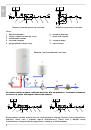
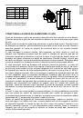
Before connecting it to the power supply, the water heater must be filled with water.
When filling the heater for the first time, the tap for the hot water on the mixing tap must be
opened. When the heater is filled with water, the water starts to run through the outlet pipe
of the mixing tap.
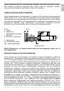
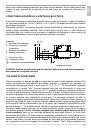
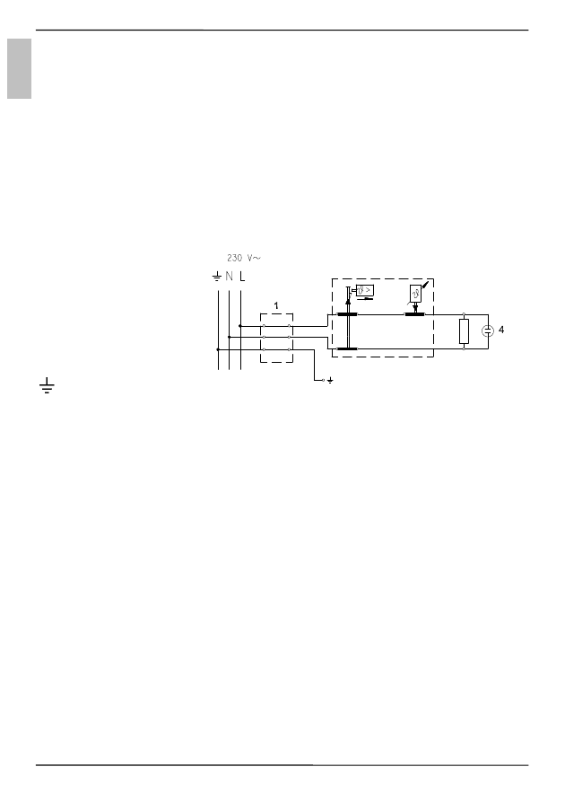
CONNECTION OF THE WATER HEATER TO THE ELECTRIC NETWORK
Before connecting to power supply network, install a power supply cord in the water heater,
with a min. diameter of 1,5 mm
2
(H05VV-F 3G 1,5 mm
2
). For it the protection plate must be
removed from the water heater. The connection of water heater to the electric network
must be performed according to standards for electric installation. Install a disconnect
switch (separating all poles from the power supply network) between the water heater and
the permanent power connection, in compliance with the national regulations.
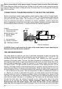
Legend:
1 - Connection terminal
2 - Thermostat and
bipolar thermal cut-out
3 - Electric heater
4 - Pilot lamp
L - Live conductor
N - Neutral conductor
- Earthing conductor
Electric installation
CAUTION: Prior to each reach in the inner of the water heater it must absolutely be
disconnected from the electric network!
USE AND MAINTENANCE
The water heater is ready for use once it has been connected to water and power. By
turning the thermostat knob, water temperature can be set between 25 °C and 75 °C. We
recommend that the knob be set to the position "eco" ensuring the most economic
operation of the water heater. This way, the water temperature is maintained at 55 °C while
the operation also results in less lime sediment as well as in less heat losses than is the
case at higher temperatures. During the operation of an electric heater can hear noise in
the wather heater. The light indicator shows the operation of the heating element. On the
casing of the water heater a bimetal thermometer is mounted, pointing clockwise (to the
right) whenever there is hot water in the water heater. When the water heater is not in use
for longer periods of time, it should be protected from freezing by setting the temperature to
"*". Do not disconnect the power. Thus the temperature of water is maintained at about 10
°C. Should you choose to disconnect the power, the water heater should be thoroughly
drained before the onset of freezing conditions. Water is discharged from heater via the
inlet pipe. For this purpose, a special fitting (T-fitting) must be mounted between the relief
valve and the heater inlet pipe, or a discharge tap. The heater can be discharged directly
through the relief valve, by rotating the handle or the rotating valve cap to the same
position as for checking the operation. Before discharge, make sure the heater is
disconnected from the power supply, and open the hot water on the connected
mixer tap. After discharging through the inlet pipe, there is still some water left in the water
E
N
3
2