
14
English
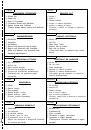
OPTIONAL ACCESSORIES (SOLD SEPARATELY)
(1) Extension Holder and Stopper
(2) Crown molding Vise Ass'y (Include Crown molding
Stopper (L))
(3) Crown molding Stopper (L)
(4) Crown molding Stopper (R)
Optional accessories are subject to change without notice.
APPLICATION
䡬
Cutting various types of aluminium sash and wood.
UNPACKING
䡬
Carefully unpack the power tool and all related items
(standard accessories).
䡬
Check carefully to make certain all related items
(standard accessories) are present.
PRIOR TO OPERATION
1. Power source
Ensure that the power source to be utilized conforms
to the power requirements specified on the product
nameplate.
2. Power switch
Ensure that the power switch is in the OFF position. If
the plug is connected to a receptacle while the trigger
switch is in the ON position, the power tool will start
operating immediately, inviting serious accident.
3. Extension cord
When the work area is removed from the power
source, use an extension cord of sufficient thickness
and rated capacity. The extension cord should be kept
as short as practicable.
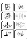
4. When the power tool is prepared for shipping, its
main parts are secured by a locking pin
Move the handle slightly so that the locking pin can
be disengaged.
CAUTION
䡬
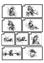
Set for transport
Lock the locking pin into the gear case (Fig. 3).
Remove a 6 mm wing bolt.Turn the turn plate as the
Fig. 5, and fix it again with the 6 mm wing bolt.
Lower guard cover the teeth of the blade to the front
of the machine.
䡬
Cutting work
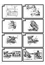
Move the handle slightly so that the locking pin can
be disengaged.
Remove a 6 mm wing bolt.Turn the turn plate as Fig.
6, and fix it again with the 6 mm wing bolt.
5. Attach the dust bag to the main unit (Fig. 1)
(1) When the dust bag has become full of sawdust, dust
will be blown out of the dust bag when the saw blade
rotates.
Check the dust bag periodically and empty it before it
becomes full.
(2) During bevel and compound cutting, attach the dust
bag at a right angle to the base surface as shown in
Fig. 4.
CAUTION
䡬
Empty the dust bag frequently to prevent the duct and
the safety cover from becoming clogged.
Sawdust will accumulate more quickly than normal
during bevel cutting.
6. Installation
Ensure that the machine is always fixed to bench.
Attach the power tool to a level, horizontal work bench.
Select 8 mm diameter bolts suitable in length for the
thickness of the work bench.
Bolt length should be at least 35 mm plus the thickness
of the work bench.
For example, use 8 mm
×
60 mm bolts for a 25 mm
thick work bench.
ADJUSTING THE POWER TOOL PRIOR TO USE
CAUTION
Make all necessary adjustments before inserting the
plug in the power source.
1. Check to see that the lower guard operates smoothly
CAUTION
䡬
This compound miter saw is equipped with a saw
head lock as safety device.
䡬
To lower the saw head to cut, the lock must be released
by pressing the lock lever (C) with your thumb.
(1) When you push down the handle while pushing the
lock lever (C), check that the lower guard revolves
smoothly (Fig. 7).
(2) Next, check that the lower guard returns to the original
position when the handle is raised.
PRACTICAL APPLICATIONS
WARNING
䡬
To avoid personal injury, never remove or place a
workpiece on the table while the tool is being
operated.
䡬
Never place your limbs inside of the line next to
warning sign while the tool is being operated. This
may cause hazardous conditions (see Fig. 8).
CAUTION
䡬
It is dangerous to remove or install the workpiece
while the saw blade is turning.
䡬
When sawing, clean off the shavings from the
turntable.
䡬
If the shavings accumulate too much, the saw blade
from the cutting material will be exposed. Never
subject your hand or anything else to go near the
exposed blade.
1. Tightly secure the material by vise assembly to be
cut so that it does not move during cutting
2. Switch operation
Pulling the trigger turns the switch on. Releasing the
trigger turns the switch off.
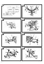
3. Holder (B), clamp lever adjustment (Fig. 9)
Attach the included holder (B) in the position as shown
in Fig. 9 and adjust the holder (B) until its bottom
surface contacts the work bench surface. After
adjustments, securely tighten the 6mm bolt with the
included 10mm box wrench. Loosen the M6
×
20 screw
on the clamp lever and attach to a position where the
clamp lever can be easily operated.
4. Using the Vise Assembly (Standard accessory) (Fig. 10)
(1) The vise assembly can be mounted on either the left
fence {Fence (B)} or the right fence {Fence (A)} by
loosening the 6 mm wing bolt (A).
(2) The screw holder can be raised or lowered according
to the height of the workpiece by loosening the 6 mm
wing bolt (B). After the adjustment, firmly tighten the
6 mm wing bolt (B) and fix the screw holder.
 1
1
 2
2
 3
3
 4
4
 5
5
 6
6
 7
7
 8
8
 9
9
 10
10
 11
11
 12
12
 13
13
 14
14
 15
15
 16
16
 17
17
 18
18
 19
19
 20
20
 21
21
 22
22
 23
23
 24
24
 25
25
 26
26
 27
27
 28
28
 29
29
 30
30
 31
31
 32
32
 33
33
 34
34
 35
35
 36
36
 37
37
 38
38
 39
39
 40
40
 41
41
 42
42
 43
43
 44
44
 45
45
 46
46
 47
47
 48
48
 49
49
 50
50
 51
51
 52
52
 53
53
 54
54
 55
55
 56
56
 57
57
 58
58
 59
59
 60
60
 61
61
 62
62
 63
63
 64
64
 65
65
 66
66
 67
67
 68
68
 69
69
 70
70
 71
71
 72
72
 73
73
 74
74
 75
75
 76
76
 77
77
 78
78
 79
79
 80
80
 81
81
 82
82
 83
83
 84
84
 85
85
 86
86
 87
87
 88
88
 89
89
 90
90
 91
91
 92
92
 93
93
 94
94
 95
95
 96
96
 97
97
 98
98
 99
99
 100
100
 101
101
 102
102
 103
103
 104
104
 105
105
 106
106