19
English
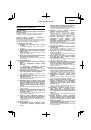
CAUTION
○
If the battery is charged while it is heated because it has
been left for a long time in a location subject to direct
sunlight or because the battery has just been used,
the pilot lamp of the charger lights for 1 second, does
not light for 0.5 seconds (o
ff
for 0.5 seconds). In such a
case,
fi
rst let the battery cool, then start charging.
○
When the pilot lamp
fl
ickers (at 0.2-second intervals),
check for and take out any foreign objects in the
charger’s battery connector. If there are no foreign
objects, it is probable that the battery or charger is
malfunctioning. Take it to your authorized Service
Center.
○
Since the built-in micro computer takes about 3
seconds to con
fi
rm that the battery being charged
with UC18YGSL is taken out, wait for a minimum of 3
seconds before reinserting it to continue charging. If
the battery is reinserted within 3 seconds, the battery
may not be properly charged.
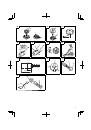
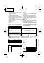
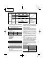
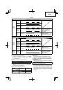
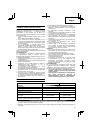
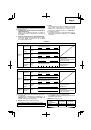
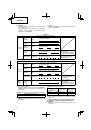
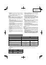
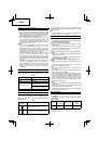
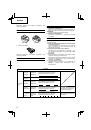
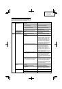
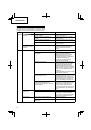
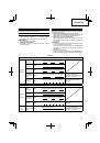
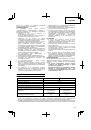
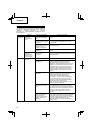
ABOUT
POWER
LAMP
The power lamp indicates various statuses for the tool.
(
Fig.
7
)
Table
4
shows the various statuses indicated by the power
lamp.
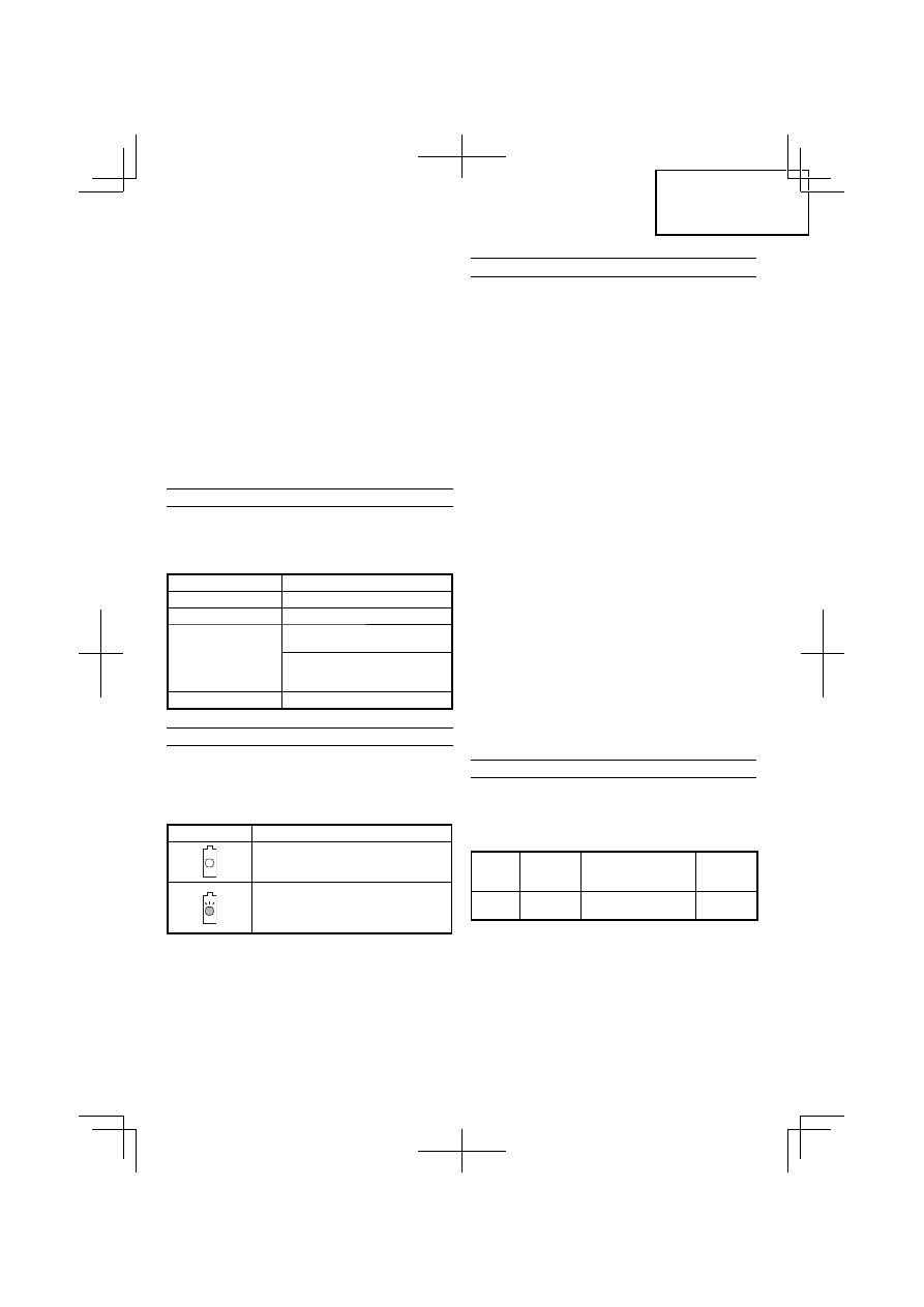
Table
4
State of lamp
Status of Tool
O
ff
Power
OFF
Red
Power ON
Blinking red
The over-heat protection circuit
of the tool is operating.
The lever is being pressed while
the overload protection circuit of
the tool is operating.
Quickly blinking red
The tool is operating abnormally.
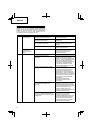
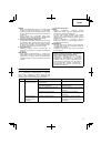
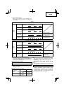
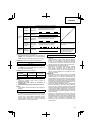
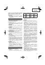
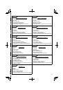
ABOUT
REMAINING
BATTERY
INDICATOR
The remaining battery lamp blinks when the remaining
battery power is low.
Please charge the tool as soon as possible. The
Table
5
shows the state of remaining battery indicator lamp and the
battery remaining power.
Table
5
State of lamp
Battery Remaining Power
The battery remaining power is
enough.
The battery remaining power is nearly
empty.
Re-charge the battery soonest
possible.
As the remaining battery indicator shows somewhat
di
ff
erently depending on ambient temperature and battery
characteristics, read it as a reference.
NOTE
Do not give a strong shock to the switch panel or break
it. It may lead to a trouble.
PRIOR
TO
OPERATION
CAUTION
Pull out battery before doing any assembly.
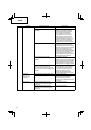
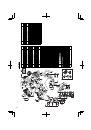
1.
Installing
the
loop
handle
(Fig.
8)
(1) Remove the M6 × 43 bolts (2 pcs.).
(2) Install the loop handle on the main pipe so that it leans
against the housing.
(3) Place the handle
fi
xture at the lower end of the main
pipe and secure it
fi
rmly using M6 × 43 bolts (2 pcs.)
and M6 nuts (2 pcs.).
NOTE
Secure the loop handle in a location that provides a
good grip.
CAUTION
Install the loop handle properly and securely as
instructed in the handling instructions.
If not attached properly or securely, it may come o
ff
and
cause injury.
2.
Installing
cover
(See
Fig.
9
and
10)
WARNING
Be sure to install the cover in its designated location.
Failure to heed this warning may result in injury from
fl
ying stones.
NOTE
Use the supplied hex. bar wrench 4 mm for installation.
(1) Use the supplied D5 tapping screw to install the knife in
the cover. (
Fig.
9
)
(2) Align the two holes in the cover bracket and the cover
and insert two M6 × 25 hex. socket button bolts. (The
cover bracket is installed in the motor case.)
(3) Place the cover holder on the underside of the cover and
use the supplied hex. bar wrench 4 mm to alternately
tighten the two M6 × 25 hex. socket button bolts until
they are properly tightened.
CAUTION
○
Take care to avoid cutting yourself on the knife inside
the cover.
○
Install the cover and knife properly and securely as
instructed in the handling instructions.
If not attached properly or securely, they may come o
ff
and cause injury.
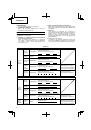
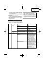
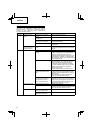
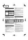
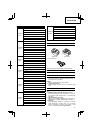
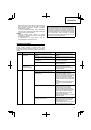
NYLON
HEAD
Installation
of
semi
-
auto
nylon
head
1.
Function
Automatically feeds more nylon cutting line when it is
tapped.
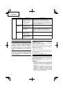
Speci
fi
cations
Code
No.
Type of
attaching
screw
Direction of rotation
Size of
attaching
screw
333903 Female
screw
Counterclockwise
M10×
P1.25-LH
Applicable nylon cord
Cord
diameter:
Φ
1.4 mm
Length: 6 m
CAUTION
○
The case must be securely attached to the cover.
○
Check the cover, case and other components for cracks
or other damage.
○
Check the case and button for wear.
If the wear limit mark on the case is no longer visible or
there is a hole in the bottom of the button, change the
new parts immediately. (
Fig.
14
)
 1
1
 2
2
 3
3
 4
4
 5
5
 6
6
 7
7
 8
8
 9
9
 10
10
 11
11
 12
12
 13
13
 14
14
 15
15
 16
16
 17
17
 18
18
 19
19
 20
20
 21
21
 22
22
 23
23
 24
24
 25
25
 26
26
 27
27
 28
28
 29
29
 30
30
 31
31
 32
32
 33
33
 34
34
 35
35
 36
36
 37
37
 38
38
 39
39
 40
40
 41
41
 42
42
 43
43
 44
44
 45
45
 46
46
 47
47
 48
48
 49
49
 50
50
 51
51
 52
52
 53
53
 54
54
 55
55
 56
56
 57
57
 58
58
 59
59
 60
60
 61
61
 62
62
 63
63
 64
64
 65
65
 66
66
 67
67
 68
68
 69
69
 70
70
 71
71
 72
72
 73
73
 74
74
 75
75
 76
76
 77
77
 78
78
 79
79
 80
80
 81
81
 82
82
 83
83
 84
84
 85
85
 86
86
 87
87
 88
88
 89
89
 90
90
 91
91
 92
92
 93
93
 94
94
 95
95
 96
96
 97
97
 98
98
 99
99
 100
100
 101
101
 102
102
 103
103
 104
104
 105
105
 106
106
 107
107
 108
108
 109
109
 110
110
 111
111
 112
112
 113
113
 114
114
 115
115
 116
116
 117
117
 118
118
 119
119
 120
120
 121
121
 122
122
 123
123
 124
124
 125
125
 126
126
 127
127
 128
128
 129
129
 130
130
 131
131
 132
132
 133
133
 134
134
 135
135
 136
136
 137
137
 138
138
 139
139
 140
140
 141
141
 142
142
 143
143
 144
144
 145
145
 146
146
 147
147
 148
148
 149
149
 150
150
 151
151
 152
152