15
2 . Web Configuration Interface
2 .3 My Targets Section
The following table describes the icons found in the
My Targets
section
Toolbar
.
Icon
Description
In the
My Targets
section, clicking the
Reload
icon refreshes the page to display the most current information.
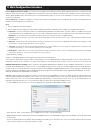
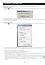
Clicking the Power icon brings up a dropdown menu of power management actions you can perform on the selected port.
Note:
In order to perform power management actions on a port, it must be configured to match a power outlet of a power
device that has been added to the KVM. (See the Power Device and Power Outlets sections of this manual for details)
Cycle
– Choose the Cycle option to perform a power cycle on the computer/server connected to the selected port.
Up
–Choose the
Up
option to turn the power to the computer/server connected to the selected port on.
Down
– Choose the
Down
option to turn the power to the computer/server connected to the selected port off.
The
Disconnect
icon allows admin accounts to disconnect users from a server port. If a server port is being accessed by
another account, highlighting the port and clicking the
Disconnect
icon terminates the remote session, making the Target
Server available for access.
Clicking on the
Display
icon initiates a remote session, with the selected port displayed. (See the
Remote Session
section
of this manual for details on managing a remote session)
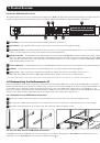
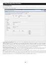
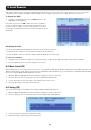
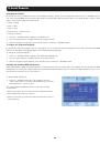
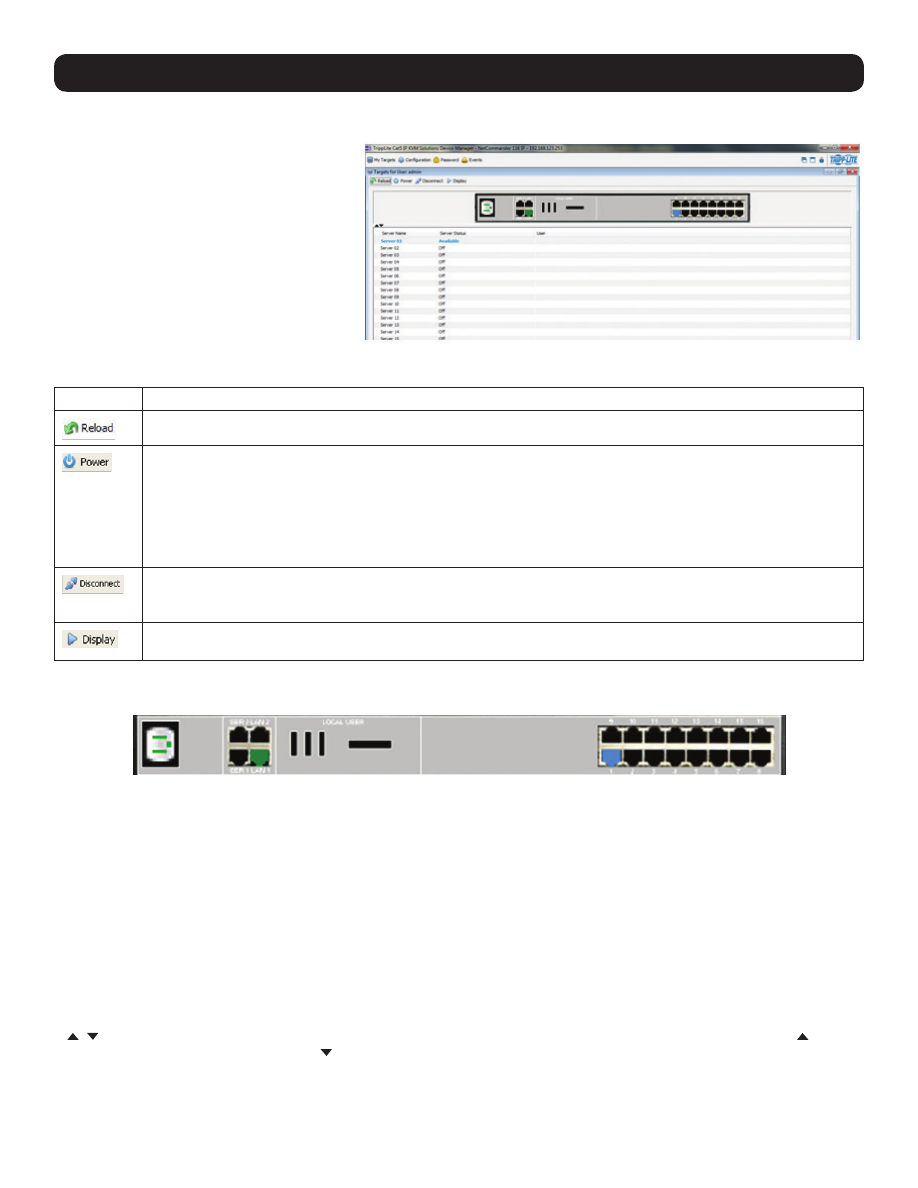
For administrators, a graphic of the KVM’s back panel is displayed in between the Toolbar and Data Pane. The features of this graphic are
described below.
•
Power Outlet –
A Green power outlet indicates that it is working. A Red power outlet indicates that it is not working properly. A Black
power outlet indicates that it is not connected.
•
Serial 1 and 2 Ports –
An Orange serial port indicates that a serial device is connected and currently being accessed by another account.
A Black serial port indicates one of three things; a device is connected and available for use, a device is connected but is not functioning
properly, or a device is not connected.
•
LAN 1 and 2 Ports –
A Green LAN port indicates that it is the active LAN port. The other LAN port will be Black. Only one LAN can be
operational at a time. When a LAN redundancy event occurs, and LAN 2 takes over for LAN 1, the LAN 1 port will be red and LAN 2 port
will be green.
•
Target Servers –
The Target Server ports will illuminate different colors to indicate their status. The different statuses are discussed in
detail in the chart on the following page. A Blue port indicates that the Target Server is
Available
; a Green port indicates that a
Remote
Session
or
Local Exclusive Session
is taking place on the Target Server; an Orange port indicates a
Remote Exclusive Session
; a Reddish
Brown port indicates a
Blocked
server status; a Black port indicates an
Off
server status; a Red port indicates a
No Communication with
Device
server status.
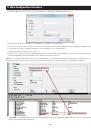
•
,
- The arrow icons to the lower-left of the back panel graphic allow the logged in account to hide or unhide it. Clicking the arrow
will hide the rear panel graphic; clicking the arrow will unhide it.
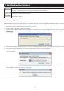
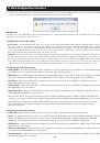
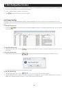
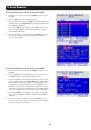
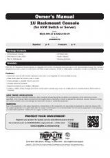
The
My Targets
section of the Web Configuration
Interface is the first page that is displayed upon
logging into the KVM remotely. This
section is
where users remotely access the connected
computers/servers and serial devices. When
accessing the
My Targets
section, only the
connected computers/servers and devices that the
logged-in account has access to are displayed in
the
Data Pane
. For administrators, a graphic of
the KVM’s back panel is displayed in between the
Toolbar
and
Data Pane
. The features of this page
are described in the following section.