Инструкция для VITEK VT-1751 BK

(скачивание инструкции бесплатно)
Формат файла: PDF
Доступность: Бесплатно как и все руководства на сайте. Без регистрации и SMS.
Дополнительно: Чтение инструкции онлайн
background image

5

ENGLISH          

switch on «ECO» mode (see switching on «ECO» 
mode above).

• 

After the finishing the operation of the fan heat-
er press the On/Off button (11), there will be a 
long sound signal, and the time left before the 
switching off (6 seconds) will appear on the dis-
play (3). After this time the unit will switch off. 

Notes: 

–  While  the  first  switching  the  heating  ele-

ment  burns,  therefore  occurrence  of  a  small 
amount of smoke or extraneous smell is pos-
sible, it is normal.

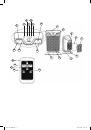
–  The  fan  heater  has  “tip-over  switch”  (button 

(9) on the lower lid of the unit body), so if you 
lift the fan heater you’ll hear a distinctive click, 
which  indicates  the  normal  operation  of  the 
tip-over switch.

–  Do  not  open  windows  or  doors  when  the  fan 

heater  is  operating.  There  should  be  good 
heat-insulation in the room; otherwise you will 
not get the desired results, due to cold air flow.

Using the Remote control

Attention!
Functions of the buttons on the remote con-
trol  fully  correspond  to  the  buttons  on  the 
control panel.

–  to replace the batteries open the battery com-

partment lid of the remote control by turning 
the  lid  to  «OPEN»  position  with  a  help  of,  for 
example,  a  coin  and  remove  old  batteries, 
then insert a new CR2032 battery.

–  Close the battery compartment lid, matching 

the arrow on the lid with a mark «OPEN»; turn 
the lid to «CLOSE» position.

Function of automatic emergency switch-off

The fan heater is equipped with function of auto-
matic emergency switch-off.
If  the  unit  starts  overheating,  automatic  thermal 
switch will be on.
–  In this case the unit will switch off automatically.
–  Remove  the  power  cord  (8)  plug  from  the 

socket.

–  Make  sure  that  the  air  inlet  and  outlet  grids 

are not blocked and nothing prevents air flow.

–  Let  the  unit  cool  down  for  approximately  20 

minutes before switching it on again.

–  Plug  the  unit  into  the  mains  and  switch  it  on 

pressing  the  button  (11).  If  the  unit  does  not 
switch  on,  it  may  mean  that  there  are  other 
damages in the unit. In this case contact the 
authorized service center for check or repair.

Cleaning and maintenance

• 

Before  cleaning  the  unit,  switch  it  off  by 
pressing  the  button  (11)  and  remove  the 
power cord (8) plug from the socket.

• 

Do  not  use  liquid  detergents,  abrasives  and 
any solvents, for example, acetone, to clean 
the unit. 

• 

To avoid the risk of fire or electric shock pro-
vide  that  water  or  other  liquid  does  not  get 
into the fan heater body.

• 

Wipe the unit body with a slightly damp cloth, 
then  wipe  it  dry.  To  remove  dust  from  the 
grids  use  a  vacuum  cleaner  with  a  corre-
sponding attachment.

• 

After cleaning put the fan to a dry cool place 
away from children for storage. 

• 

Before  starting  the  unit,  check  the  technical 
condition of the unit, the power cord plug and 
the power cord (8) insulation.

Cleaning the filter (6)

–  Remove the inlet filter grid (7).
–  Remove the filter (6), wash it and dry.
–  Install filter (6) back in its place.
–  Install the inlet filter grid (7) back in its place; 

make sure that all the clamps go to their cor-
responding openings.

ATTENTION! 

Portable  electric  fan  heaters  are 

intended for additional rooms heating. They are 
not meant for operation as main heating units.

Technical specifications

Power supply: 220-240 V, ~ 50 Hz
Power: 2000 W
Heating area: up to 20 m

2

The manufacturer preserves the right to change 
the  specifications  of  the  unit  without  a  prelimi-
nary notification

Unit operating life is 5 years.

Guarantee 

Details  regarding  guarantee  conditions  can  be  ob-
tained  from  the  dealer  from  whom  the  appliance  was 
purchased. The bill of sale or receipt must be produced 
when making any claim under the terms of this guar-
antee.

This  product  conforms  to  the  EMC-
Requirements  as  laid  down  by  the  Council 
Directive 89/336/EEC and to the Low Voltage 
Regulation (73/23 EEC)

VT-1751 IM.indd   5

04.06.2012   14:11:11

1
2
3
4
5
6
7
8
9
10
11
12
13
14
15
16
17
18
19
20
21
22
23
24
25
26
27
28
29
30
31
32
33
34
35
36
37
38
39
40
Оглавление инструкции
  • Страница 1 из 41
    1 VT-1751 IM.indd 1 04.06.2012 14:11:10
  • Страница 2 из 41
    16 15 11 18 17 14 19 3 4 5 6 10 12 7 13 1 20 2 8 9 21 22 23 VT-1751 IM.indd 2 24 04.06.2012 14:11:10
  • Страница 3 из 41
    ENGLISH FAN HEATER • • Description 1. Base 2. Front grid 3. Display 4. Control panel 5. Carrying handle 6. Inlet filter 7. Inlet filter grid 8. Power cord 9. Tip-over switch • • • Control panel 10. Oscillation function On/Off button 11. On/Off button 12. Timer/Delayed start On/Off button 13.
  • Страница 4 из 41
    ENGLISH • • Avoid contact of the power cord with hot and sharp subjects. • If foreign smell or noise appears, stop using the unit immediately. • Do not switch on the unit if the power cord or the plug is damaged, if the unit malfunctions or in case the unit fell. In this case contact the authorized
  • Страница 5 из 41
    ENGLISH Cleaning and maintenance • Before cleaning the unit, switch it off by pressing the button (11) and remove the power cord (8) plug from the socket. • Do not use liquid detergents, abrasives and any solvents, for example, acetone, to clean the unit. • To avoid the risk of fire or electric
  • Страница 6 из 41
    DEUTSCH HEIZLÜFTER – Es ist nicht gestattet, den Stecker in die beschädigten und abgenutzten Steckdosen zu stecken. Beschreibung 1. Untersatz 2. Vordergitter 3. Display 4. Steuerungsplatte 5. Tragegriff 6. Eingangsfilter 7. Gitter des Eingangsfilters 8. Netzkabel 9. Umkippschutzsystem • • •
  • Страница 7 из 41
    DEUTSCH • verständliche Anweisungen über sichere Nutzung des Geräts und die Gefahren bei seiner falschen Nutzung gibt. Es ist nicht gestattet, das Gerät beim Abschalten vom Stromnetz am Netzkabel zu ziehen, halten Sie es am Stecker. • Berühren Sie nie den Netzstecker mit nassen Händen. • Es ist
  • Страница 8 из 41
    DEUTSCH Achtung! Bevor Sie die Funktion der Einschaltrückstellung des Heizlüfters benutzen, wählen Sie die gewünschte Betriebsstufe, indem Sie die Taste (14) berühren, z.B. schalten Sie den „ECO“-Betrieb ein (über Einschaltung des „ECO“-Betrieb siehe oben.) • Nach der Beendigung des Betriebs des
  • Страница 9 из 41
    DEUTSCH ACHTUNG! Tragbare elektrische Heizlüfter sind für die zusätzliche Beheizung der Räume geeignet. Diese sind für die Nutzung als Hauptheizgeräte nicht geeignet. – Ziehen Sie den Netzstecker (8) aus der Steckdose. – Vergewissern Sie sich, dass die Gitter der ein- und austretenden Luft nicht
  • Страница 10 из 41
    русский – Запрещается вставлять вилку электро- ТЕПЛОВЕНТИЛЯТОР сетевого шнура в неисправные или изношенные розетки. Описание 1. Подставка 2. Передняя решетка 3. Дисплей 4. Панель управления 5. Ручка для переноски 6. Входной фильтр 7. Решетка входного фильтра 8. Сетевой шнур 9. Система защиты при
  • Страница 11 из 41
    русский • • Перед тем как вынуть вилку сетевого шнура из розетки, установите переключатель режимов работы в положение выключено. • При отсоединении вилки сетевого шнура от электрической розетки держитесь за вилку, а не за сам шнур. • Не прикасайтесь к вилке сетевого шнура мокрыми руками. •
  • Страница 12 из 41
    русский • – Режим предотвращения замерзания «Anti-freeze» (19) • В режиме «ECO» вы можете установить температуру воздуха, которую устройство во время работы будет поддерживать в помещении. Прикосновением к кнопке (11) включите устройство, прикосновением к кнопке (14) выберите режим работы «ЕСО»,
  • Страница 13 из 41
    русский • Использование пульта дистанционного управления Внимание! Функции кнопок на пульте дистанционного управления полностью соответствуют кнопкам на панели управления. – Для замены элемента питания откройте крышку батарейного отсека пульта ДУ, повернув крышку в положение «OPEN», например, с
  • Страница 14 из 41
    Қазақ ЖЫЛУЖЕЛДЕТКІШ – Жылужелдеткішті оның тікелей міндеті Сипаттамасы 1. Тіреу 2. Алдыңғы тор 3. Дисплей 4. Басқару тақтасы 5. Тасымалдауға арналған сап 6. Кіргізетін сүзгіш 7. Кіргізетін сүзгіш торы 8. Желілік бау 9. Аударылу кезіндегі қорғаныс жүйесі – Алғашқы іске қосу алдында, электр бойынша
  • Страница 15 из 41
    Қазақ • • • • • • • • • • • • • • • • туындылас қызмет көрсету орталығына хабарласыңыз. • Балалардың қауіпсіздігі мақсатында орау ретінде пайдаланылатын полиэтилен қаптарды қараусыз қалдырмаңыз. Назар аударыңыз! Балаларға полиэтилен қаптармен немесе пленкамен ойнауға рұқсат етпеңіз. Тұншығу қаупі
  • Страница 16 из 41
    Қазақ • Батырманы (14) басып құрылғының қажетті жұмыс режимін таңдаңыз, жұмыс режимдері дисплейде (3) пиктограммалар түрінде көрсетіледі: – Бөлмедегі ауаның ауаның қызуының төмен деңгейі – Бөлмедегі ауаның ауаның қызуының жоғары деңгейі – «ECO» режимі (15) – «Желдеткіш» режимі (16) – Мұздың қатуына
  • Страница 17 из 41
    Қазақ – Кіріп жатқан және шығып жатқан ауаның Ескерту: – Алғашқы іске қосу кезінде қыздырғыш элемент күйеді, сондықтан біршама түтін немесе бөтен иіс бөлінуі мүмкін, бұл қалыпты құбылыс. – Жылужелдеткіштің аударылудан қорғаныс жүйесі бар (корпустың төменгі қақпағында батырма (9)), сондықтан егер
  • Страница 18 из 41
    Қазақ – Кіргізетін сүзгіштің торын (7) орнына орнатыңыз, барлық ілгектер сәйкес саңылауларға тиюін қадағалаңыз. НАЗАР АУДАРЫҢЫЗ! Тасымалданатын электрлік жылытқыштар бөлмені қосымша жылыту үшін арналған. Олар негізгі жылытқыш аспап ретінде жұмыс істеу үшін арналмаған. Техникалық сипаттамалары
  • Страница 19 из 41
    romÂnĂ/ Moldovenească AEROTERMĂ – Înainte de a porni aparatul verificaţi dacă tensiunea reţelei electrice corespunde cu cea înscrisă pe corpul aparatului. – Nu introduceţi fişa cablului de alimentare în prize defecte sau uzate. Descriere 1. Suport 2. Grilaj frontal 3. Afişaj 4. Panou de comandă 5.
  • Страница 20 из 41
    romÂnĂ/ Moldovenească corespunzătoare şi clare de către persoana responsabilă de siguranţa lor cu privire la folosirea sigură a aparatului şi despre riscurile care pot apărea în caz de folosire inadecvată. Întotdeauna deconectaţi aparatul prin tragerea fişei, şi nu prin tragerea cablului. • Nu
  • Страница 21 из 41
    romÂnĂ/ Moldovenească «-» puteţi seta temperatura necesară de încălzire a aerului în încăpere între +16оС şi +32оС. Dacă temperatura aerului din încăpere va scădea cu aproximativ 3 grade aparatul automat va începe să funcţioneze în regimul de încălzire a aerului, iar în cazul în care temperatura
  • Страница 22 из 41
    romÂnĂ/ Moldovenească Curăţarea filtrului (6): Scoateţi grilajul filtrului de intrare (7). Extrageţi filtrul (6), spălaţi-l şi uscaţi-l. Instalaţi filtrul (6) în poziţia iniţială. Instalaţi grilajul filtrului de intrare (7) în poziţia iniţială, verificaţi facă toate închizătoarele au nimerit în
  • Страница 23 из 41
    Český Český TEPELNÝ VENTILÁTOR • Popis 1. Podstavec 2. Přední mřížka 3. Displej 4. Ovládací panel 5. Rukojeť pro přenášení 6. Vstupní filtr 7. Mřížka vstupního filtru 8. Napájecí kabel 9. Ochranný systém při převrácení • • • Ovládací panel • 10. Tlačítko „zapnuto/vypnuto“ funkce otočení 11.
  • Страница 24 из 41
    Český • • Aby se zabránilo popálení, vyhněte se kontaktu s horkými povrchy mřížky a působení vycházejícího horkého vzduchu na otevřené části těla. • Nepřenášejte přístroj za napájecí kabel. • Nenamotávejte kabel kolem přístroje. • Nedovolujte, aby se kabel dotýkal horkých a ostrých předmětů. •
  • Страница 25 из 41
    Český Funkce automatického nouzového vypnutí Zařízení je vybaveno funkcí automatického nouzového vypnutí. Pokud se přístroj začne přehřívat, spustí se automatická tepelná pojistka. – V tomto případě se přístroj automaticky vypne. – Vytáhněte zástrčku napájecího kabelu (8) ze zásuvky. – Ujistěte
  • Страница 26 из 41
    Český VAROVÁNÍ! Přenosné elektrické tepelné ventilátory se používají pro přitápění. Nemohou sloužit jako hlavní ohřívací přístroje. Technické parametry Napájení: 220-240 V ~ 50 Hz Výkon: 2000 W. Plocha vytápění: až 20 m2 Výrobce si vyhrazuje právo měnit technické parametry zařízení bez předchozího
  • Страница 27 из 41
    УКРАЇНЬСКИЙ – Забороняється вставляти вилку електро- ТЕПЛОВЕНТИЛЯТОР мережевого шнура в несправні або зношені розетки. Опис 1. Підставка 2. Передня решітка 3. Дисплей 4. Панель управління 5. Ручка для перенесення 6. Вхідний фільтр 7. Решітка вхідного фільтру 8. Мережевий шнур 9. Система захисту при
  • Страница 28 из 41
    УКРАЇНЬСКИЙ • можливостями, якщо лише особою, що відповідає за їх безпеку, їм не дані відповідні і зрозумілі ним інструкції про безпечне використання пристрою і тієї небезпеки, яка може виникати при його неправильному використанні. При від’єднанні вилки мережевого шнура від електричної розетки
  • Страница 29 из 41
    УКРАЇНЬСКИЙ необхідний час відстрочення включення пристрою. Для включення функції доторкніться до кнопки (12), при цьому на дисплеї (3) спалахне піктограма (17), дотиком до кнопок (13) «+» «-» встановите час, після закінчення якого станеться включення пристрою. Час відстрочення включення можна
  • Страница 30 из 41
    УКРАЇНЬСКИЙ • – Закрийте кришку батарейного відсіку, поєднавши стрілку на кришці з відміткою «OPEN», оберніть кришку в положення «CLOSE». Функція автоматичного аварійного відключення Пристрій оснащений функцією автоматичного аварійного відключення. Якщо пристрій почне перегріватися, то спрацює
  • Страница 31 из 41
    Беларускi • ЦЕПЛАВЕНТЫЛЯТАР Апісанне 1. Падстаўка 2. Пярэдняя рашотка 3. Дысплей 4. Панэль кіравання 5. Ручка для пераноскі 6. Уваходны фільтр 7. Рашотка ўваходнага фільтра 8. Сеткавы шнур 9. Сістэма абароны пры перакульванні • • • Панэль кіравання 10. Кнопка «укл/выкл» функцыі павароту 11. Кнопка
  • Страница 32 из 41
    Беларускi • • Пры адлучэнні вілкі сеткавага шнура ад электрычнай разеткі трымайцеся за вілку, а не за сам шнур. • Не датыкайцеся да вілкі сеткавага шнура мокрымі рукамі. • Забараняецца апускаць прыладу ў ваду і любыя іншыя вадкасці. • Не выкарыстоўвайце прыладу ў ванных пакоях ці ў памяшканнях з
  • Страница 33 из 41
    Беларускi (магчымы час працы прылады ад 0,5 гадзіны да 24 гадзін). • Калі прылада выключана, але пры гэтым вілка сеткавага шнура (8) ўстаўлена ў сеткавую разетку, вы можаце ўсталяваць неабходны час адтэрміноўкі ўключэння прылады. Для ўключэння функцыі дакраніцеся да кнопкі (12), пры гэтым на
  • Страница 34 из 41
    Беларускi рашотках можна выкарыстоўваць пыласос з адпаведнай насадкай. • Пасля чысткі цеплавентылятара прыбярыце яго на захоўванне ў сухое прахалоднае месца, недаступнае для дзяцей. • Перад наступным уключэннем абавязкова праверце тэхнічны стан прылады, стан вілкі сеткавага шнура і ізаляцыі
  • Страница 35 из 41
    ISITISH VЕNTILYATОRI Ўзбек – Birinchi mаrtа ishlаtishdаn оldin elеktr tаrmоg’idаgi quvvаt jihоz ishlаydigаn elеktr quvvаtigа to’g’ri kеlishini tеkshirib ko’ring. – Elеktr vilkаsini nоsоz yoki eskirgаn rоzеtkаgа ulаsh tа’qiqlаnаdi. • Yong’in chiqmаsligi uchun jihоzni rоzеtkаgа ulаgаndа o’tkаzgich
  • Страница 36 из 41
    Ўзбек Ishlаtish Isitish vеntilyatоrini tеkis, qimirlаmаydigаn jоygа qo’ying, hаvо kirish jоylаri birоr buyum bilаn to’silib qоlmаsligi kеrаk. Elеktr vilkаsini хo’l qo’l bilаn ushlаmаng. Jihоzni suvgа yoki bоshqа suyuqlikkа sоlish tа’qiqlаnаdi. • Jihоzni vаnnахоnаdа yoki nаmlik ko’p хоnаlаrdа
  • Страница 37 из 41
    Jihоzgа хоnа hаrоrаti tushgаndа ishlаb kеtаdigаn «Anti-freeze» hоlаtidа ishlаsh imkоniyati qo’yilgаn. Ish hоlаtini tаnlаsh tugmаsigа (14) qo’l tеkkizib «Anti-freeze» hоlаtini tаnlаng, displеydа (3) shu hоlаtdа ishlаyotgаni bеlgisi (18, 19), bеlgilаb qo’yilgаn o’zi ishlаb kеtаdigаn hаrоrаt
  • Страница 38 из 41
    Ўзбек Tоzаlаsh vа tехnik хizmаt qilish • Tоzаlаshdаn оdin «ishlаtish/o’chirish» tugmаsigа (11) qo’l tеkkizib isitish vеntilyatоrini o’chiring, elеktr shnuridаgi (8) vilkаsini rоzеtkаdаn chiqаrib оling. • Tоzаlаsh uchun suyuq yuvish vоsitаlаrini, qirib tоzаlаydigаn vоsitаlаrni, eritgichlаr, misоl
  • Страница 39 из 41
    gb A production date of the item is indicated in the serial number on the technical data plate. A serial number is an eleven-unit number, with the first four figures indicating the production date. For example, serial number 0606ххххххх means that the item was manufactured in June (the sixth month)
  • Страница 40 из 41
    VT-1751 IM.indd 40 04.06.2012 14:11:17
  • Страница 41 из 41