13
XENYX X2442USB/X2222USB/X1832USB/X1622USB User Manual
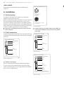
FBQ FEEDBACK DETECTION
The switch turns on the FBQ Feedback Detection System. It uses the LEDs in the
frequency band faders to indicate the critical frequencies. On a per-need basis,
lower the frequency range in question somewhat in order to avoid feedback.
The graphic stereo equalizer has to be turned on in order to use this function.
◊
Logically, at least one (ideally several) microphone channels have to be
open for feedback to occur at all!
Feedback is particularly common when stage monitors (“wedges”) are
concerned, because monitors project sound in the direction of microphones.
Therefore, you can also use the FBQ Feedback Detection for monitors by placing
the equalizer in the monitor bus (see MAIN MIX/MONITOR).
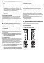
4. Digital Effects Processor
24-BIT MULTI-EFFECTS PROCESSOR
Here you can find a list of all presets stored in the multi-effects processor.
This built-in effects module produces high-grade standard effects such as reverb,
chorus, flanger, delay and various combination effects. Use the Aux Send
FX
on
the channels and the Aux Send
FX
master control to determine the input signal of
the effects processor.
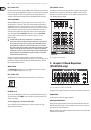
X1832USB
Fig. 4.1: Digital effects module
The built-in stereo effects processor has the advantage that it does not need to
be wired up. This excludes the danger of humming or level mismatch right from
the start and thus considerably facilitates use.
These effect presets are classical “mixing effects”. If you move the STEREO AUX
RETURN FX control, you mix the channel signal (dry) and the effect signal. You can
control the balance between the two signals with the channel fader and the
STEREO AUX RETURN FX control.
FX OUT
Mixing consoles X2222USB and X2442USB have a separate output for the effects
device, which is unbalanced and stereo (tip = left signal; ring = right signal;
sleeve = ground/shielding). Thus, you can record, for example, a vocal track
enhanced with reverb in parallel to a “dry” vocal track; when doing the mix-down
later on, you can freely determine the amount of reverb added.
◊
The X2442USB has the effect output on the rear, X2222USB has it
located next to the aux sends on the front panel.
FX FOOTSW.
Connect a standard foot switch to the foot switch jack and use this to switch
the effects processor on and off. A light at the bottom of the display indicates
wheater the effects processor has been muted by the foot switch.
◊
In Chapter 6.2 you will find an illustration showing how to connect your
foot switch correctly.
LEVEL
The LED level meter on the effects module should display a sufficiently high
level. Take care to ensure that the clip LED only lights up at peak levels. If it is
lit constantly, you are overloading the effects processor and this could cause
unpleasant distortion.
PROGRAM
You can select the effect preset by turning the
PROGRAM
control. The display
flashes with the number of the current preset. To recall the selected preset,
press on the button; the flashing stops. You can also recall the selected preset
with the foot switch.
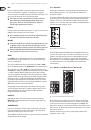
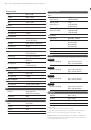
5. Rear Panel Connectors
5.1 Main mix outputs, insert points and control
room outputs
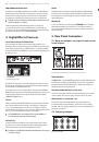
X2442USB
Fig. 5.1: Main Mix outputs, main mix insert points and control room outputs
MAIN OUTPUTS
The
MAIN
outputs carry the MAIN MIX signal and are on balanced XLR jacks with
a nominal level of +4 dBu. In parallel with this, ¼" phone jacks carry the main
mix signal in a balanced format (X1622USB: here, the phone jack outputs are
unbalanced and located on the front panel).
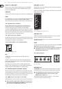
CONTROL ROOM OUTPUTS (CTRL OUT)
The control room output is normally connected to the monitoring system in the
control room and carries the stereo mix or, when selected, the solo signals.
MAIN INS(ERTS) (X2442USB only)
These are the insert points for the main mix. In the signal path, they are
post-main mix amp, but pre-main fader(s). Use them to insert, for example,
a dynamics processor or graphic equalizer. Please also note the information on
insert points in chapter 5.3.
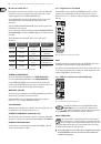
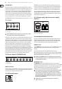
5.2 Subgroup outputs
Fig. 5.2: Subgroup outputs