14
XENYX X2442USB/X2222USB/X1832USB/X1622USB User Manual
SUB OUTPUTS
The subgroup outputs are unbalanced and provide the mix of those channels
assigned to each subgroup with the SUB switch (X2442USB: switches 1-2 or 3-4)
next to the channel faders. Thus, you can, for example, route a subgroup to a
second console or use the output as a recording output in parallel to the main
outputs. In this way, you can record several tracks simultaneously. With an
8-track recorder, use Y cables and wire the inputs of your machine so that you
have 2 x 4 tracks available (e.g. channel 1 to track 1 and 2, etc.). In the first pass,
you can record the tracks 1, 3, 5 and 7, in the second the tracks 2, 4, 6 and 8.
The XENYX 2442FX already has subgroup outputs wired in parallel (1-5, 2-6, etc.).
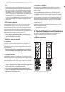
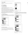
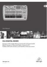
5.3 Inserts
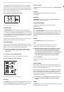
X1622USB
Fig. 5.3: Insert points
◊
On the 2442FX the channel insert points are located on the control
panel between the line input and the GAIN control.
Insert points are very useful to process channel signals with dynamic processors
or equalizers. Unlike reverb or other effects devices, whose signals are usually
added to the dry signal, dynamic processors are most effective on the complete
signal. In this case, aux send paths are a less-than-perfect solution. It is better
to interrupt the signal path and insert a dynamic processor and/or equalizer.
After processing, the signal is routed back to the console at precisely the same
point it left. However, the channel signal path is interrupted only if a plug is
inserted into the corresponding jack (stereo phone plug: tip = signal output;
ring = return input). All mono input channels are equipped with inserts. They are
pre-fader, pre-EQ and pre-aux send. Inserts can also be used as pre-EQ direct
outputs, without interrupting the signal path. To this end, you will need a cable
fitted with mono phone plugs on the tape machine or effect device end, and a
bridged stereo phone plug on the console side (tip and ring connected).
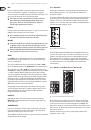
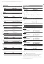
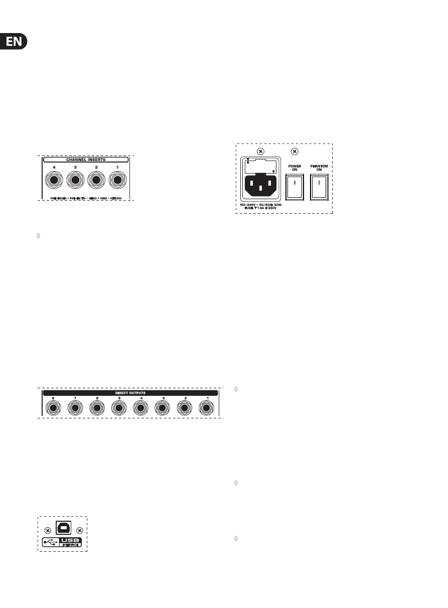
5.4 Direct outputs (X2442USB only)
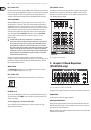
X2442USB
Fig. 5.4: Direct outputs
DIRECT OUTPUTS
The direct outputs of the X2442USB (1 each per mono input channel) are ideal for
recording if several tracks are to be recorded simultaneously. These unbalanced
phone jacks are post-EQ, post-mute and post-fader.
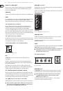
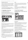
5.5 USB input/output
Fig. 5.5: USB input/output
The XENYX mixer line has built-in USB connectivity, allowing stereo signals to
be sent to and from the mixer and a computer. The audio sent from the mixer to
a computer is identical to the MAIN MIX. Audio being sent to the mixer from a
computer can be routed to the main mix with the 2-TR/USB TO MAIN button.
Connect the USB type B plug into the USB jack on the mixer, and the other end
into a free USB port on your computer. There are no required drivers, but we
recommend that PC users install the included ASIO driver. The driver can also be
downloaded from behringer.com.
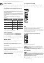
5.6 Voltage supply, phantom power supply
and fuse
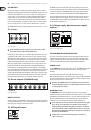
All Models
Fig. 5.6: Voltage supply and fuse
FUSE HOLDER/IEC MAINS RECEPTACLE
The console is connected to the mains via the cable supplied, which meets the
required safety standards. Blown fuses must only be replaced by fuses of the
same type and rating. The mains connection is made via a cable with IEC mains
connector. An appropriate mains cable is supplied with the equipment.
POWER switch
Use the
POWER
switch to turn on the mixing console. The POWER switch should
always be in the “Off” position when you are about to connect your unit to
the mains.
To disconnect the unit from the mains, pull out the main cord plug.
When installing the product, ensure that the plug is easily accessible. If mounting
in a rack, ensure that the mains can be easily disconnected by a plug pull or by an
all-pole disconnect switch on or near the rack.
◊
Attention: The POWER switch does not fully disconnect the unit from
the mains. Unplug the power cord completely when the unit is not used
for prolonged periods of time.
PHANTOM switch
The
PHANTOM
switch activates the phantom power (necessary to operate
condenser microphones) on the XLR sockets of the mono channels. The red
+48 V
LED illuminates when phantom power is on. As a rule, dynamic microphones can
still be used with phantom power, provided that they are wired in a balanced
configuration. In case of doubt, contact the microphone manufacturer!
◊
Connect microphones before you switch on the phantom power supply.
Please do not connect microphones to the mixer (or the stagebox/
wallbox) while the phantom power supply is switched on. In addition,
the monitor/PA loud-speakers should be muted before you activate the
phantom power supply. After switching on, wait approx. one minute to
allow for system stabilization.
◊
Caution! Please also note the information given in chapter 6.2.1
“Audio connections”.