15
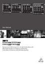
XENYX X2442USB/X2222USB/X1832USB/X1622USB User Manual
SERIAL NUMBER
Please note the important information on the serial number given in
chapter 1.3.3.
6. Installation
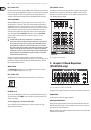
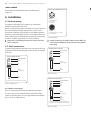
6.1 Rack mounting
The packaging of your mixing console contains two 19" rack mounts for
installation on the side panels of the console.
Before you can attach the rack mounts to the mixing console, you need to remove
the screws holding the left and right side panels. Then, use these screws to
fasten the two rack mounts, each specifically to one side. With the rack mounts
installed, you can mount the mixing console in a commercially available 19" rack.
Be sure to allow for proper air flow around the unit, and do not place the mixing
console close to radiators or power amps, so as to avoid overheating.
◊
Only use the screws holding the mixing console side panels to fasten
the 19" rack mounts.
6.2 Cable connections
You will need a large number of cables for the various connections of the console.
The illustrations below show the wiring of these cables. Be sure to use only high-
grade cables.
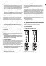
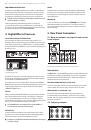
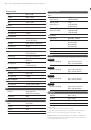
strain relief clamp
sleeve
tip
sleeve
pole 1/ground
tip
pole 2
The footswitch connects both poles momentarily
¼" TS footswitch connector
Fig. 6.1: Foot switch connector
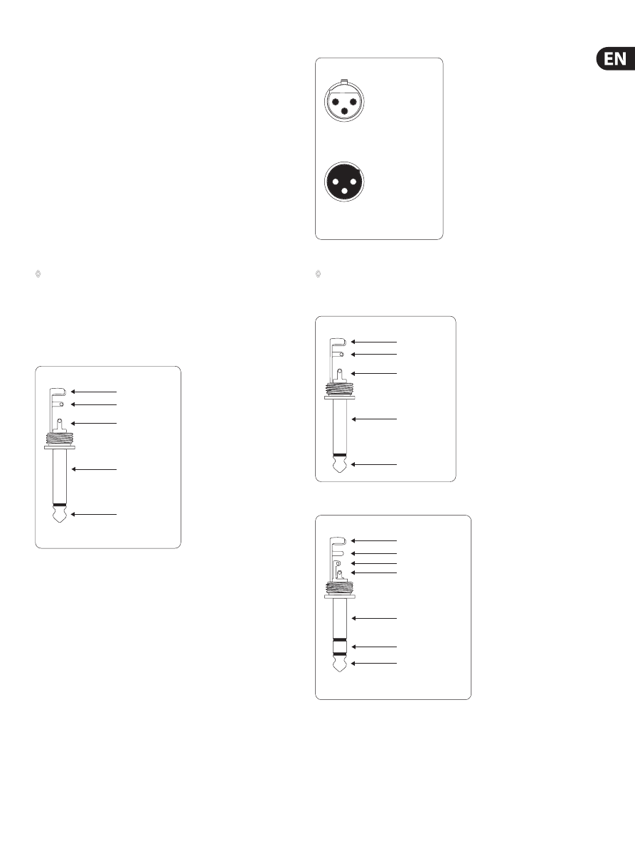
6.2.1 Audio connections
Please use commercial RCA cables to wire the 2-track inputs and outputs.
You can, of course, also connect unbalanced devices to the balanced input/
outputs. Use either mono plugs, or use stereo plugs to link the ring and shaft (or
pins 1 & 3 in the case of XLR connectors).
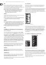
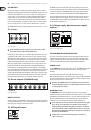
output
For unbalanced use, pin 1 and pin 3
have to be bridged
1 = ground/shield
2 = hot (+ve)
3 = cold (-ve)
input
1
2
3
1
2
3
Balanced use with XLR connectors
Fig. 6.2: XLR connections
◊
Caution! You must never use unbalanced XLR connectors (PIN 1 and
3 connected) at the MIC input jacks if you want to use the phantom
power supply.
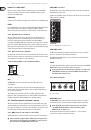
strain relief clamp
sleeve
tip
sleeve
(ground/shield)
Unbalanced ¼" TS connector
tip
(signal)
Fig. 6.3: ¼" mono plug
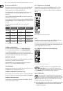
strain relief clamp
sleeve
ring
tip
sleeve
ground/shield
For connection of balanced and unbalanced plugs,
ring and sleeve have to be bridged at the stereo plug.
Balanced ¼" TRS connector
ring
cold (-ve)
tip
hot (+ve)
Fig. 6.4: ¼" stereo plug