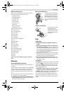
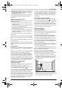
16
| English
1 618 C00 99J | (10.10.13)
Bosch Power Tools
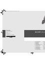
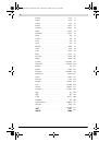
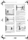
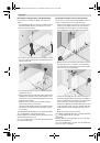
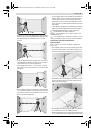
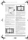
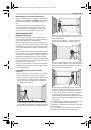
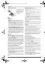
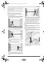
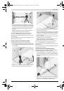
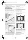
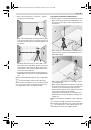
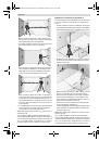
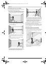
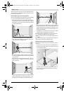
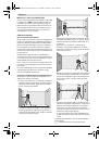
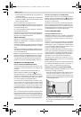
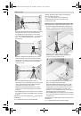
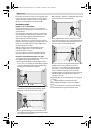
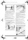
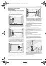
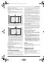
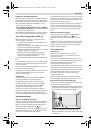
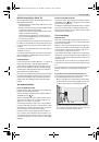
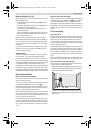
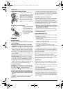
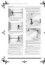
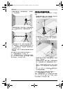
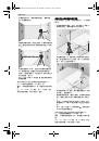
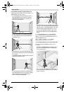
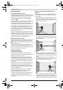
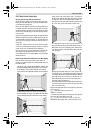
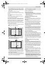
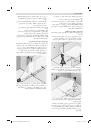
Checking the Levelling Accuracy of the Horizontal Line
For the check, a free surface of approx. 5 x 5 metres is re-
quired.
– Set up the measuring tool on a firm, level surface between
both walls A and B. Allow the measuring tool to level in
while in horizontal operation.
– At a distance of 2.5 metres from the measuring tool, mark
the centre of the laser line (point
I
on wall A and point
II
on
wall B) on both walls.
– Set up the measuring tool 5 metres away turned by 180°
and allow it to level in.
– Align the height of the measuring tool (using a tripod or by
underlaying, if required) in such a manner that the centre
of the laser line is projected exactly against the previously
marked point
II
on wall B.
– Mark the centre of the laser line as point
III
(vertically
above or below point
I
) on the wall A.
– The difference
d
of both marked points
I
and
III
on wall A
indicates the actual deviation of the measuring tool from
the level plane.
The maximum permitted deviation d
max
is calculated as follows:
d
max
= double distance of the walls x 0.3 mm/m
Example: With a 5 metre distance between the walls, the max-
imum deviation must not exceed
d
max
= 2 x 5 m x 0.3 mm/m = 3 mm. Thus, the marks must not
be more than 3 mm apart.
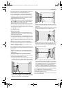
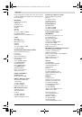
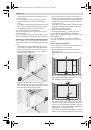
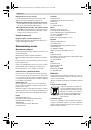
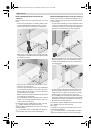
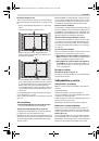
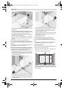
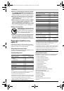
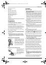
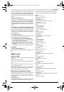
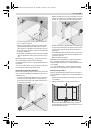
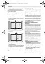
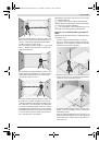
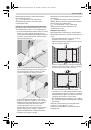
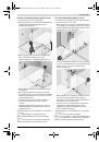
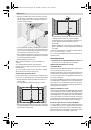
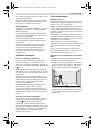
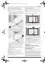
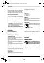
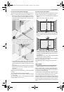
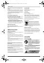
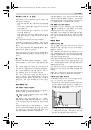
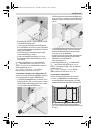
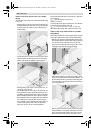
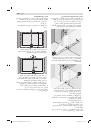
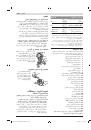
Checking the Levelling Accuracy of the Vertical Line
For this check, a door opening is required with at least 2.5 m
of space (on a firm surface) to each side of the door.
– Position the measuring tool on a firm, level surface (not on
a tripod) 2.5 m away from the door opening. Allow the
measuring tool to level in while in cross-line operation
mode, and direct the laser beams at the door opening.
– Mark the centre of the vertical laser line at the floor of the
door opening (point
I
), at a distance of 5 m beyond the
other side of the door opening (point
II
) and at the upper
edge of the door opening (point
III
).
– Position the measuring tool on the other side of the door
opening directly behind point
II
. Allow the measuring tool
to level in and align the vertical laser line in such a manner
that its centre runs exactly through points
I
and
II
.
– The difference
d
between point
III
and the centre of the la-
ser line at the upper edge of the door opening results in the
actual deviation of the measuring tool from the vertical
plane.
– Measure the height of the door opening.
The maximum permitted deviation d
max
is calculated as follows:
d
max
= double height of the door opening
x 0.3 mm/m
Example: With a door opening height of 2 metres, the maxi-
mum permitted deviation is
d
max
= 2 x 2 m x 0.3 mm/m = 1.2 mm. Thus, the marks must
not be more than 1.2 mm apart.
2,5 m
,0 m
5,
5
A
B
d
2,5 m
A
B
2,5 m
2,5 m
2 m
d
OBJ_BUCH-1973-002.book Page 16 Thursday, October 10, 2013 4:45 PM
 1
1
 2
2
 3
3
 4
4
 5
5
 6
6
 7
7
 8
8
 9
9
 10
10
 11
11
 12
12
 13
13
 14
14
 15
15
 16
16
 17
17
 18
18
 19
19
 20
20
 21
21
 22
22
 23
23
 24
24
 25
25
 26
26
 27
27
 28
28
 29
29
 30
30
 31
31
 32
32
 33
33
 34
34
 35
35
 36
36
 37
37
 38
38
 39
39
 40
40
 41
41
 42
42
 43
43
 44
44
 45
45
 46
46
 47
47
 48
48
 49
49
 50
50
 51
51
 52
52
 53
53
 54
54
 55
55
 56
56
 57
57
 58
58
 59
59
 60
60
 61
61
 62
62
 63
63
 64
64
 65
65
 66
66
 67
67
 68
68
 69
69
 70
70
 71
71
 72
72
 73
73
 74
74
 75
75
 76
76
 77
77
 78
78
 79
79
 80
80
 81
81
 82
82
 83
83
 84
84
 85
85
 86
86
 87
87
 88
88
 89
89
 90
90
 91
91
 92
92
 93
93
 94
94
 95
95
 96
96
 97
97
 98
98
 99
99
 100
100
 101
101
 102
102
 103
103
 104
104
 105
105
 106
106
 107
107
 108
108
 109
109
 110
110
 111
111
 112
112
 113
113
 114
114
 115
115
 116
116
 117
117
 118
118
 119
119
 120
120
 121
121
 122
122
 123
123
 124
124
 125
125
 126
126
 127
127
 128
128
 129
129
 130
130
 131
131
 132
132
 133
133
 134
134
 135
135
 136
136
 137
137
 138
138
 139
139
 140
140
 141
141
 142
142
 143
143
 144
144
 145
145
 146
146
 147
147
 148
148
 149
149
 150
150
 151
151
 152
152
 153
153
 154
154
 155
155
 156
156
 157
157
 158
158
 159
159
 160
160
 161
161
 162
162
 163
163
 164
164
 165
165
 166
166
 167
167
 168
168
 169
169
 170
170
 171
171
 172
172
 173
173
 174
174
 175
175
 176
176
 177
177
 178
178
 179
179
 180
180
 181
181
 182
182
 183
183
 184
184
 185
185
 186
186
 187
187
 188
188
 189
189
 190
190
 191
191
 192
192
 193
193
 194
194
 195
195
 196
196
 197
197
 198
198
 199
199
 200
200
 201
201
 202
202
 203
203
 204
204
 205
205
 206
206
 207
207
 208
208
 209
209
 210
210
 211
211
 212
212
 213
213
 214
214
 215
215
 216
216
 217
217
 218
218
 219
219
 220
220
 221
221
 222
222
 223
223
 224
224
 225
225
 226
226
 227
227
 228
228
 229
229
 230
230
 231
231
 232
232
 233
233
 234
234
 235
235
 236
236
 237
237
 238
238
 239
239