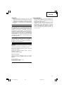
English
14
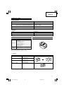
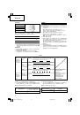
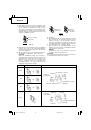
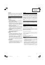
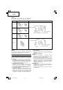
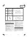
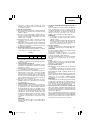
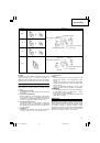
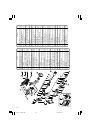
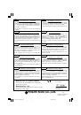
Fig. 21
(4) Attachment
1
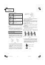
When using an M6, M8 or M10 cutter
Insert the cutter in the cutter attachment groove on
the bracket, insert the special spacer between the
cutter and the bracket and then use the hex. socket
hd. bolt to tighten and secure.
2
When using the W3/8" cutter
Insert the cutter in the cutter attachment groove on
the bracket and then use the hex. socket hd. bolt
to tighten and secure.
NOTE:
Spacers are not required when using the W3/8"
cutter.
CAUTION:
The hex. socket hd. bolt should be sufficiently tightened
with the hexagonal wrench.
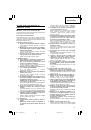
2. Changing the cutter attachment direction or replacing
the cutter
(1) Before removing:
1
Pull the trigger switch and move bracket (A), stopping
with the cutter in the open position.
2
Set the forward/reverse switching button to the lock
position (
Fig. 5 (b)
).
3
Remove the rechargeable battery from the main
unit.
(2) Removal
Use the accessory hexagonal bar wrench to remove
the hex. socket hd. bolt. It is now possible to remove
the cutter and spacer.
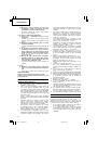
(3) Before attaching
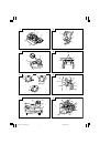
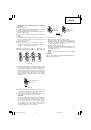
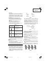
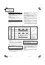
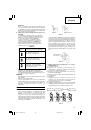
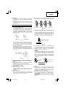
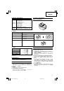
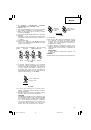
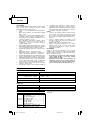
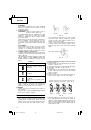
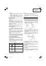
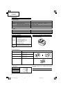
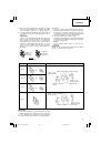
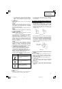
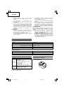
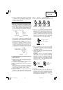
1
There are four edges on the cutter. As shown in
Fig. 19
, by changing the position of the edge it is
possible to use the blade four times.
Fig. 19
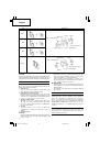
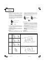
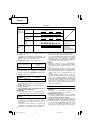
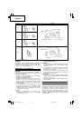
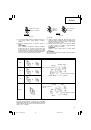
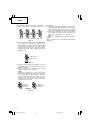
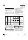
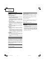
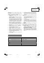
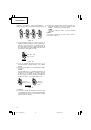
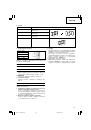
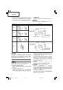
2
There is directionality for cutter attachment in order
to change the position of the edge. Check that the
cutter has been attached so that the side without
the notch on the cutter can be seen on bracket (A)
(movable side) when seen from the main unit viewed
from the front or that the notch on the cutter
surface on bracket (B) (fixed side) can be seen (
Figs.
6
and
20
).
Fig. 20
3
If there is breakage or warping on the cutter edge
or if there are bulges on the cutter attachment
surface, use a file to the areas flat.
4
Use brush to remove the filings attached to the
cutter attachment groove on the bracket.
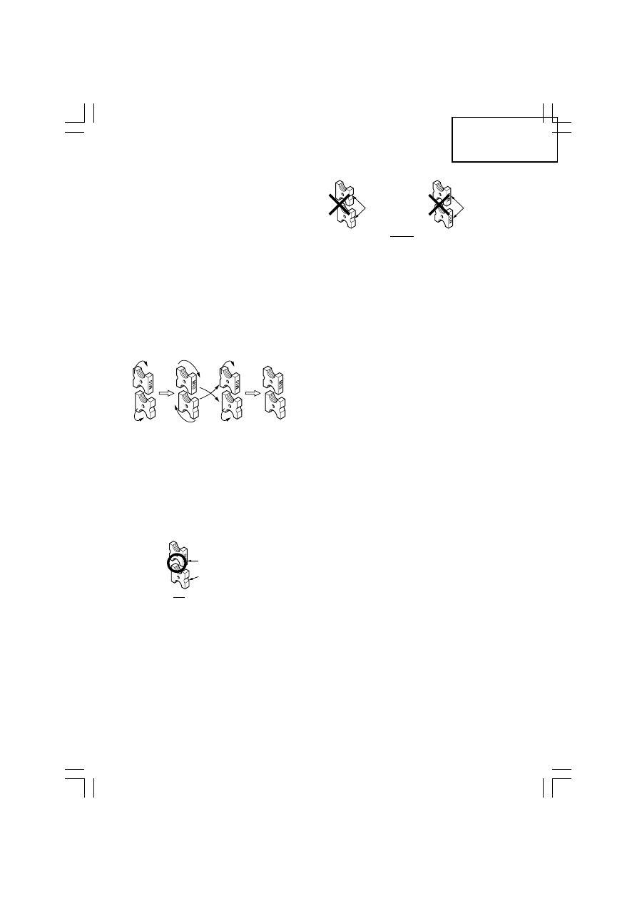
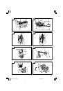
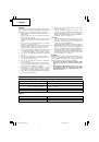
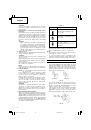
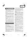
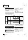
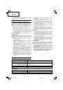
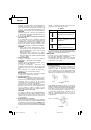
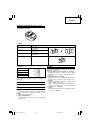
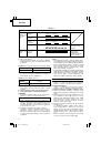
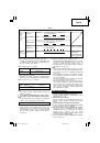
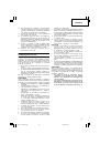
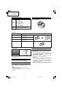
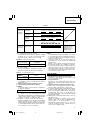
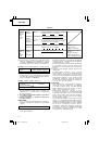
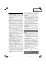
CAUTION:
As shown in
Fig. 21
, if the cutters are combined
in such a way that both side without the notch on
the cutter or both notch sides are facing out, the
pitch of the threads on the studs and the threads
on the cutter will not be in agreement. This can
cause damage to the cutter edge or cause wear to
premature damage to the main unit.
1st time
2nd time
3rd time
4th time
(
)
(
)
Turning to
the back side
(
)
Re-
insertion
(
)
Turning to
the back side
Turning to
the back side
Notch side
Side without notch
DO
Both on
notch side
Both on
side without
notch
DON’T
01Eng_CL14DSL_EE
08/3/26, 18:30
14
 1
1
 2
2
 3
3
 4
4
 5
5
 6
6
 7
7
 8
8
 9
9
 10
10
 11
11
 12
12
 13
13
 14
14
 15
15
 16
16
 17
17
 18
18
 19
19
 20
20
 21
21
 22
22
 23
23
 24
24
 25
25
 26
26
 27
27
 28
28
 29
29
 30
30
 31
31
 32
32
 33
33
 34
34
 35
35
 36
36
 37
37
 38
38
 39
39
 40
40
 41
41
 42
42
 43
43
 44
44
 45
45
 46
46
 47
47
 48
48
 49
49
 50
50
 51
51
 52
52
 53
53
 54
54
 55
55
 56
56
 57
57
 58
58
 59
59
 60
60
 61
61
 62
62
 63
63
 64
64
 65
65
 66
66
 67
67
 68
68
 69
69
 70
70
 71
71
 72
72
 73
73
 74
74
 75
75
 76
76
 77
77
 78
78
 79
79
 80
80
 81
81
 82
82
 83
83
 84
84
 85
85
 86
86
 87
87
 88
88
 89
89
 90
90
 91
91
 92
92
 93
93
 94
94
 95
95
 96
96
 97
97
 98
98
 99
99
 100
100
 101
101
 102
102
 103
103
 104
104
 105
105
 106
106
 107
107
 108
108
 109
109
 110
110
 111
111
 112
112