English
12
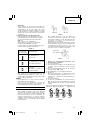
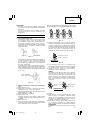
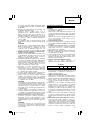
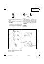
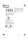
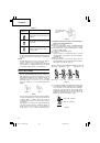
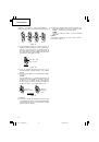
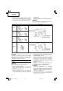
stopping operations, set the forward/reverse
switching button to the lock position (
Fig. 5 (b)
).
(3) Push the forward/reverse switching button from the
left as shown in
Fig. 5 (c)
. With the button held
down, pull the trigger switch so that the cutter can
be removed from the stud. Only set to this position
if the rechargeable battery is worn out and the unit
stops operating during cutting. Immediately turn off
the switch after the cutter has been removed from
the stud.
If you remove your finger, the forward/reverse
switching button automatically returns to the lock
position (
Fig. 5 (b)
).
CAUTION:
Do not attempt to cut in the reverse position (
Fig.
5 (c)
). If you attempt to cut in this position, there
will be an overload on the motor and cutting will
not be possible. Never apply excessive force to the
main unit as this can cause damage to the unit.
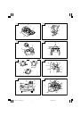
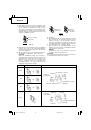
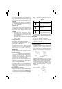
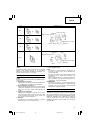
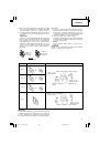
4. Check the cutter size, attachment direction,
attachment bolt and spacer
(1) The cutter size differs according to the size of the
studs to be cut. Make sure that a cutter is attached
that conforms to the size of the studs to be cut.
(2) Cutter attachment includes directionality. Make sure
that the cutter has been attached so that the side
without the notch on the cutter can be seen on
bracket (A) (movable side) when the main unit is
viewed from the front or that the notch on the cutter
surface can be seen on bracket (B) (fixed side).
(3) Use the accessory hexagonal wrench to insure that
the hex. socket hd. bolt for attaching the cutter is
securely tightened (
Fig. 6
). Using the equipment
while the bolt is loose could cause damage to the
main unit and cutter.
(4) Depending on the size of the studs it may be
necessary to attach special spacers to the cutter.
1
When using the M10, M8 or M6 cutter
Check and confirm that the accessory M6, M8 or
M10 spacers are correctly inserted respectively
between bracket (A) and the cutter and bracket (B)
and the cutter (
Fig. 6
).
CAUTION:
If the spacers are not attached or if spacers of the
wrong size are used, the threads of the cutter and
the studs will not properly mesh, thereby causing
damage to the studs and the cutter edge. Be sure
to attach spacers correctly.
2
When using the W3/8" cutter
No spacers are required. Check and confirm that
only the cutter is attached.
For details, refer to the section on “Cutter life and
replacement”.
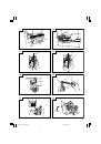
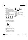
5. Correctly insert the stud guide
The stud guide is used to prevent tilting during
cutting of studs. Correctly adjust the dial calibration
to the mark (
) depending on the size of the stud
to be cut (
Fig. 7
).
CAUTION:
If the size of the stud and the dial position to do
not agree, the cut section may be subjected to burrs
or its shape may be distorted, which may result in
damage to the main unit.
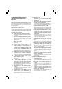
HOW TO USE
CAUTION:
䡬
Never bring the cutter near your fingers when
operating the trigger switch.
䡬
When cutting short studs, take caution as to not
place your fingers in the space between the short
stud and main unit, such as the guard section (see
Fig. 8
), battery, etc.
䡬
After cutting, the cut section of the stud is very
sharp and therefore dangerous. Be very careful
when handling the stud.
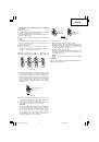
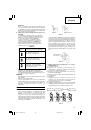
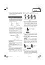
1. Normal Cutting Method
(1) Pull the trigger switch and move bracket (A), stopping
with the cutter in the open position shown in
Fig.
8
.
(2) As shown in
Fig. 9
, set the stud to be cut in the
cutter on the bracket (B) side, making sure that the
threads correctly mesh with each other.
(3) While maintaining the stud in a horizontal position,
pull the trigger switch all the way to cut the stud
(
Fig. 8
).
(4) After cutting turn off the switch with bracket (A)
facing directly upward. The unit stops with the
cutter in the open position, thus making it easier
to proceed to the next operation.
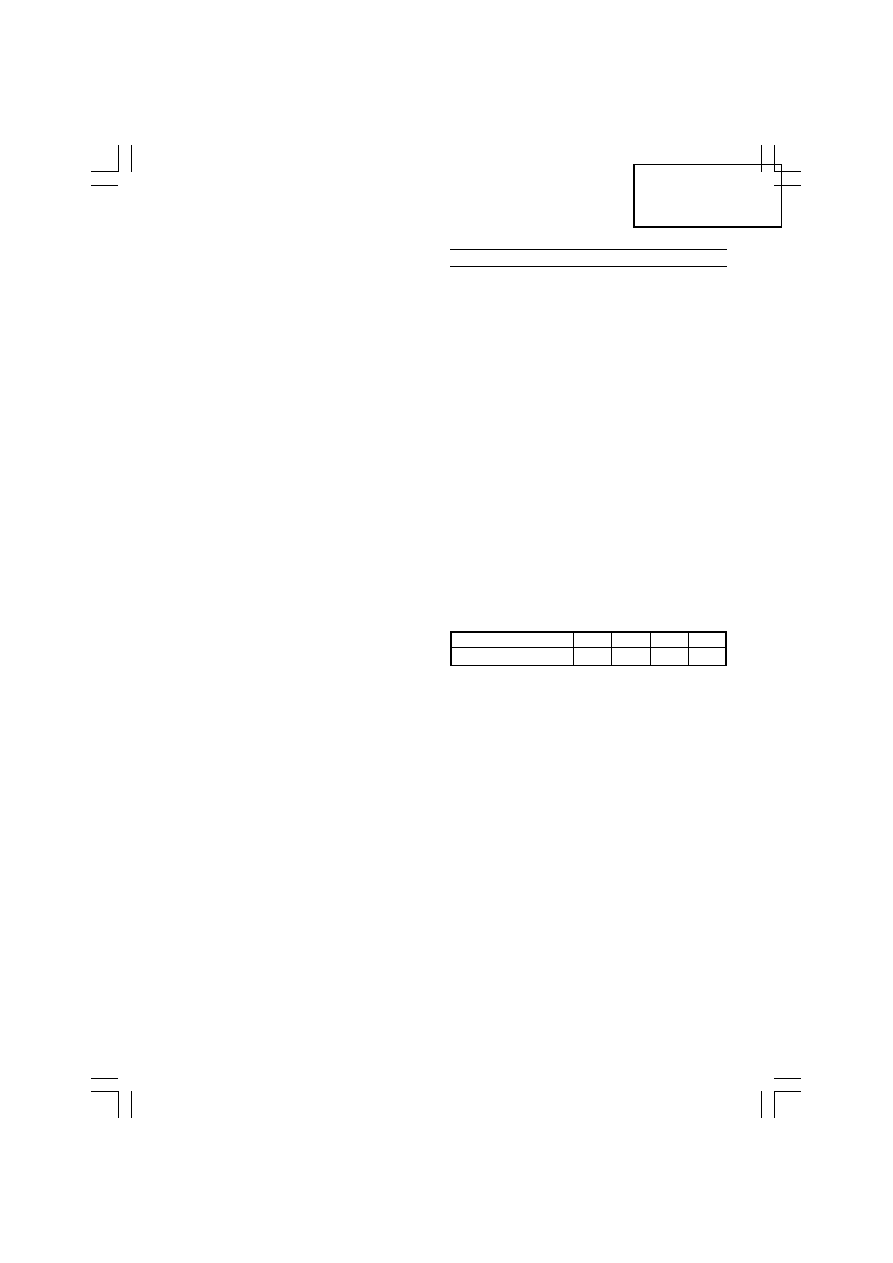
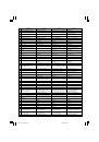
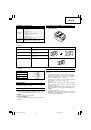
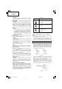
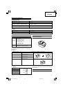
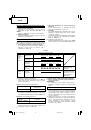
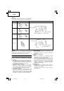
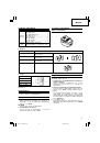
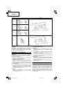
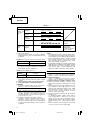
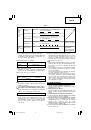
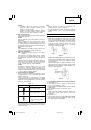
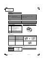
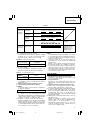
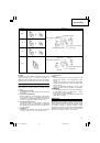
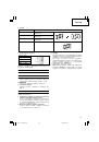
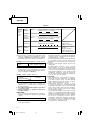
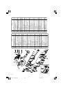
2. Number of cuttings (per battery charging)
Refer to the chart below for the number of cuttings
per battery charging.
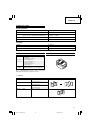
Table 4
Battery
M10
M8
M6
W3/8"
BSL1430
660
1020
1520
740
The number of cuttings can also vary somewhat
according to the ambient temperature, characteristics
of the battery and the condition of the cutter.
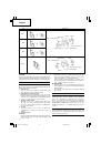
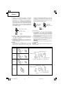
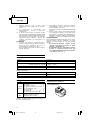
3. Cutting fixed lengths (Fig. 10)
When cutting several studs to the same length,
using the equipment in the following way will making
cutting operations more efficient.
(1) First cut one stud to the required length, and then
use it as a fixed length guide.
(2) Insert the stud used as a fixed length guide in the
stud attachment hole found on the main unit stud
guide and use the hexagonal bar wrench to tighten
and secure the hex. socket hd. bolt. Adjust at this
time so that the distance between the end of the
stud used as a fixed length and the cutter is the
necessary length.
(3) Insert the stud for cutting in the cutter, aligning the
end with that of the stud used as a cutting guide,
and then cut the stud.
4. Cutting studs that are already secured (Fig. 11)
When cutting studs that are suspended from the
ceiling or secured to walls or floors.
When inserting the stud in the cutter, the meshing
of the stud thread and cutter thread is unstable. In
such a case, after inserting the stud in the cutter,
lightly pull the trigger switch to close the cutter at
low speed and then completely mesh the stud and
the upper and lower cutters. Next, pull the trigger
switch all the way to cut the stud.
01Eng_CL14DSL_EE
08/3/26, 18:30
12
 1
1
 2
2
 3
3
 4
4
 5
5
 6
6
 7
7
 8
8
 9
9
 10
10
 11
11
 12
12
 13
13
 14
14
 15
15
 16
16
 17
17
 18
18
 19
19
 20
20
 21
21
 22
22
 23
23
 24
24
 25
25
 26
26
 27
27
 28
28
 29
29
 30
30
 31
31
 32
32
 33
33
 34
34
 35
35
 36
36
 37
37
 38
38
 39
39
 40
40
 41
41
 42
42
 43
43
 44
44
 45
45
 46
46
 47
47
 48
48
 49
49
 50
50
 51
51
 52
52
 53
53
 54
54
 55
55
 56
56
 57
57
 58
58
 59
59
 60
60
 61
61
 62
62
 63
63
 64
64
 65
65
 66
66
 67
67
 68
68
 69
69
 70
70
 71
71
 72
72
 73
73
 74
74
 75
75
 76
76
 77
77
 78
78
 79
79
 80
80
 81
81
 82
82
 83
83
 84
84
 85
85
 86
86
 87
87
 88
88
 89
89
 90
90
 91
91
 92
92
 93
93
 94
94
 95
95
 96
96
 97
97
 98
98
 99
99
 100
100
 101
101
 102
102
 103
103
 104
104
 105
105
 106
106
 107
107
 108
108
 109
109
 110
110
 111
111
 112
112