9
Be aware that the RMB-1555 and RMB-1585 are capable of high power
levels, in excess of
120 watts and 200 watts respectively per channel.
Make sure that your speakers can handle the power of the amplifier. If in
doubt about your speakers, ask your local Rotel audio dealer for advice.
These amplifiers are straightforward in their installation and operation. If
you have experience with other stereo power amplifiers, you shouldn’t find
anything perplexing. Simply plug in the associated components and enjoy.
A Few Precautions
WARNING:
To avoid potential damage to your system, turn off ALL the
components in the system when connecting or disconnecting the loudspeakers
or any associated components. Do not turn the system components back on
until you are sure all the connections are correct and secure. Pay particular
attention to the speaker wires. There must be no loose strands that could
contact the other speaker wires, or the chassis of the amplifier.
Please read this manual carefully. In addition to installation and operating
instructions, it provides valuable information on various system configurations
as well as general information that will help you get optimum performance
from your system. Please contact your authorized Rotel dealer for answers to
any questions you might have. In addition, all of us at Rotel welcome your
questions and comments.
Save the shipping carton and all enclosed packing material for future use.
Shipping or moving the amplifier in anything other than the original packing
material may result in severe damage that is not covered by the warranty.
If included in the box please fill out and send in the owner`s registration
card. Also be sure to keep the original sales receipt. It is your best record
of the date of purchase, which you will need in the event warranty service
is required.
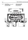
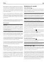
Placement
The RMB-1555 and RMB-1585 generate heat as part of its normal operation.
The heat sinks and ventilation openings in the amplifier are designed to
dissipate this heat. The ventilation slots in the top cover must be open.
There should be 10 cm (4 inches) of clearance around the chassis, and
reasonable airflow through the installation location, to prevent the amplifier
from overheating.
Remember the weight of the amplifier when you select an installation location.
Make sure that the shelf or cabinet can support it. We recommend installing
the unit in furniture designed to house audio components. Such furniture is
designed to reduce or suppress vibration which can adversely affect sound
quality. Ask your authorized Rotel dealer for advice about component
furniture and proper installation of audio components.
AC Power and Control
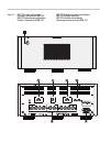
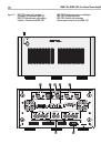
AC Power Input
7
Your amplifier is configured at the factory for the proper AC voltage in the
country where you purchased it, either 120 volts or 230 volts. The AC line
configuration is noted on a decal on the back panel.
NOTE:
Should you move your amplifier to another country, it may be
possible to reconfigure it for use on a different line voltage. Do not attempt
to perform this conversion yourself. Opening the enclosure of the amplifier
exposes you to dangerous voltages. Consult a qualified service person or
the Rotel factory service department for information.
NOTE:
Some products are intended for sale in more than one country and
as such are supplied with more than one AC cord. Please use only the cord
appropriate for your country/region.
Because of its high power rating, the amplifier can draw considerable current.
Therefore, it should be plugged directly into a wall outlet. The RMB-1555
and RMB-1585 must be plugged into a 3-pin polarized outlet. Do not use
an extension cord. A heavy duty multi-tap power outlet strip may be used
if it (and the wall outlet) is rated to handle the current demanded by the
amplifier and all the other components connected to it.
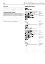
Be sure the POWER SWITCH
1
on the front panel of the amplifier is
turned off (in the “out” position). Then, connect the supplied power cord to
the Power Connector
7
on the rear of the unit and the AC power outlet.
If you are going to be away from home for an extended period of time
such as a month-long vacation, it is a sensible precaution to unplug your
amplifier (as well as other audio and video components) while you are away.
Power Switch and Power Indicator
1
The power switch is located on the front panel of your amplifier. To turn the
amplifier on, push the switch in. The ring around the switch will light up,
indicating that the amplifier is turned on. To turn the amplifier off, push the
button again and return it to the “out” position.
NOTE:
Place the self adhesive ring over the light surrounding the Power
switch if the blue light is too bright.
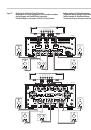
Trigger ON/OFF Mode Selector
5
The amplifier provides the option for manual or automatic power on/off
operation. These modes are selectable using a toggle switch on the back panel.
With the switch in the +12V TRIGGER ON position, the amplifier is turned
on automatically when a 12V trigger signal is present at the 3.5 mm
Jack of TRIGGER IN on the rear panel. The amplifier will go into standby
mode if the +12V signal is not present. The front panel POWER SWITCH
overrides this function. It must be ON for the +12V trigger to work. Turning
the switch OFF cuts power to the amplifier, regardless of whether or not a
trigger signal is present.
12 Volt Trigger Input and Output
5
The jack labeled IN is for connecting the 3.5mm Plug/Cable carrying a
+12 volt trigger signal to turn the amplifier on and off. To use this feature
the toggle switch must be set to the ON position. This input accepts any
control signal (AC or DC) ranging from 3 volts to 30 volts.
The jack labeled OUT is for connecting another 3.5mm plug/cable to
provide a 12V trigger signal to other components. The 12V output signal is
available whenever a +12 volt trigger signal is applied to the IN connector.
Protection Circuitry
1
The RMB-1555 and RMB-1585 feature thermal and over-current protection
circuits that protect against potential damage in the event of extreme or
faulty operating conditions. Unlike many designs, these protection circuits are
independent of the audio signal and have no impact on sonic performance.
Instead, the protection circuits monitors the temperature of the output devices
and the current they are handling and shuts down the amplifier if operating
conditions exceed safe limits.