5
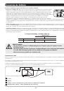
Operation
Switch Modes
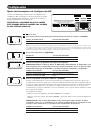
After configuring, mounting and connecting your Inverter/Charger, you are able to operate it by switching between the following operating
modes as appropriate to your situation:
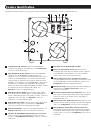
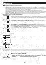
AUTO/REMOTE:
Switch to this mode when you need constant, uninterrupted AC power for connected appliances and
equipment. The Inverter/Charger will continue to supply AC power to connected equipment and to charge your connected
batteries while utility- or generator-supplied AC power is present. Since the inverter is ON (but in Standby) in this mode, it
will automatically switch to your battery system to supply AC power to connected equipment in the absence of a utility/
generator source or in over/under voltage situations. “AUTO/REMOTE” also enables an optional remote control module
(Tripp Lite model APSRM4, sold separately) to function when connected to the unit.
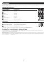
CHARGE ONLY:
Switch to this mode when you are not using connected appliances and equipment in order to conserve
battery power by disabling the inverter. The Inverter/Charger will continue to pass through AC power to connected
equipment and charge connected batteries while utility- or generator-supplied AC power is present. However, since the
inverter is OFF in this mode, it WILL NOT supply AC power to connected equipment in the absence of a utility/generator
source or in over/under voltage situations.
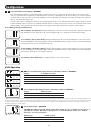
OFF:
Switch to this mode to shut down the Inverter/Charger completely, preventing the inverter from drawing power from
the batteries, and preventing utility AC from passing through to connected equipment or charging the batteries. Use this
switch to automatically reset the unit if it shuts down due to overload or overheating. First remove the excessive load or
allow the unit to sufficiently cool (applicable to your situation). Switch to “OFF”, then back to “AUTO/REMOTE” or
“CHARGE ONLY” as desired. If unit fails to reset, remove more load or allow unit to cool further and retry.
NOTE:
The optional remote control module (APSRM4) will only reset overloads.
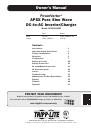
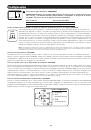
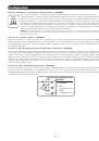
Indicator Lights
Your Inverter/Charger (and Tripp Lite’s optional APSRM4 Remote Control Module, sold separately) is equipped with a simple, intuitive,
user-friendly set of indicator lights. These easily-remembered “traffic light” signals will allow you, shortly after first use, to tell at a glance
the charge condition of your batteries, as well as ascertain operating details and fault conditions.
LINE Green Indicator:
If the operating mode switch is set to “AUTO/REMOTE,” this light will ILLUMINATE CONTINUOUSLY
when your connected equipment is receiving continuous AC power supplied from a utility/generator source.
If the operating mode switch is set to “CHARGE ONLY,” this light will FLASH to alert you that the unit’s inverter is OFF and
will NOT supply AC power in the absence of a utility/generator source or in over/under voltage situations.
INV (Inverting) Yellow Indicator:
This light will ILLUMINATE CONTINUOUSLY whenever connected equipment is receiving
battery-supplied, inverted AC power (in the absence of a utility/generator source or in over/under voltage situations). This
light will be off when AC power is supplying the load. This light will FLASH to alert you if the load is less than the Battery
Charge Conserver (Load Sense) setting.
LOAD Red Indicator:
This red light will ILLUMINATE CONTINUOUSLY whenever the inverter is functioning and the power
demanded by connected appliances and equipment exceeds 100% of load capacity. The light will FLASH to alert you
when the inverter shuts down due to a severe overload or overheating. If this happens, turn the operating mode switch
“OFF”; remove the overload and let the unit cool. You may then turn the operating mode switch to either “AUTO/REMOTE”
or “CHARGE ONLY” after it has adequately cooled. This light will be off when AC power is supplying the load.
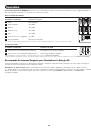
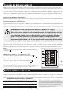
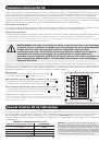
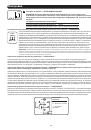
Position =
Position –
(Position ø)
OPERATION
LINE
INV
LOAD
CHARGE
ONLY
AC POWER
IN / OUT
RMT
BATT
TEMP
RMT
GEN
START
AUTO/
REMOTE
OFF
ALTERNATIVE
POWER SOURCE
MODEL: APSX6048VR
INVERTER RATING:
INPUT: 48V , 145A
OUTPUT: 208/230V~, 50/60Hz, 6000W
CHARGER RATING:
INPUT: 208/230V~, 50/60Hz
OUTPUT: 48V , 23/90A
BYPASS RATING:
INPUT: 208/230V~, 50/60Hz, 30A MAX
OUTPUT: 208/230V~, 50/60Hz,
6000W @ 230V
5500W @ 208V
NOTE: TOTAL INPUT CURRENT IS 30A MAX
Front white silkscreen on unit
artwork for:
APSX6048VR
96-7281
200705058
1 2 3 4
5 6 7 8
9 1011
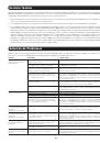
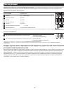
OPERATION
LINE
INV
LOAD
CHARGE
ONLY
AC POWER
IN / OUT
RMT
BATT
TEMP
RMT
GEN
START
AUTO/
REMOTE
OFF
CONFIGURATION DIP SWITCHES
(SEE MANUAL OR TOP OF UNIT FOR INSTRUCTIONS)
ALTERNATIVE
POWER SOURCE
MODEL: APSX6048VR
INVERTER RATING:
INPUT: 48V , 145A
OUTPUT: 208/230V~, 50/60Hz, 6000W
CHARGER RATING:
INPUT: 208/230V~, 50/60Hz
OUTPUT: 48V , 23/90A
BYPASS RATING:
INPUT: 208/230V~, 50/60Hz, 30A MAX
OUTPUT: 208/230V~, 50/60Hz,
6000W @ 230V
5500W @ 208V
NOTE: TOTAL INPUT CURRENT IS 30A MAX
Front white silkscreen on unit
artwork for:
APSX6048VR
96-7281
200705058
1 2 3 4
5 6 7 8
9 101112
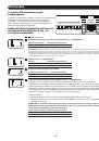