8
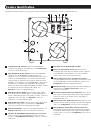
Configuration
7
,
8
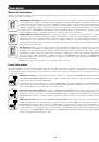
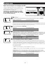
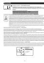
Select AC Input Current Sharing—OPTIONAL
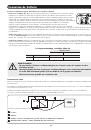
Your Inverter/Charger features a high-output battery charger that can draw a significant amount of AC power from your utility
source or generator when charging at its maximum rate. If your unit is supplying its full AC power rating to its connected heavy
electrical loads at the same time as this high charging occurs, the AC input circuit breaker could trip, resulting in the complete
shut off of pass-though utility power.
To reduce the chance of tripping this breaker, all Inverter/Chargers are pre-set to automatically limit the input current as described
in “Most Limiting” below. If your unit is equipped with DIP switches 7 and 8, they may be used to select other AC input current
sharing settings. Verify that AC input wiring is rated for the higher current that results when using the other settings.
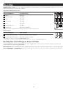
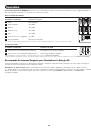
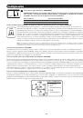
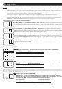
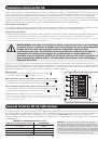
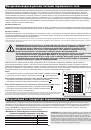
Select Battery Charger-Limiting Points
“Most Limiting” (#7 & #8 Up):
Charger-limiting takes effect the moment any AC load is applied; charger output
falls gradually from full output at no AC load passing through to no output at full load (factory setting).
“Less Limiting” (#7 Up & #8 Down):
Charger-limiting begins when the Inverter/Charger’s load reaches 33% of
the Inverter/Charger’s load rating. Charger output falls gradually from full output at 33% of the Inverter/Charger’s
load rating to about 33% of full output at full load.
“Least Limiting” (#7 Down & #8 Up):
Charger-limiting begins when the Inverter/Charger’s load reaches 66% of
the Inverter/Charger’s load rating. Charger output falls gradually from full output at 66% of the Inverter/Charger’s
load rating to about 66% of full output at full load.
“No Limiting” (#7 & #8 Down):
No charger-limiting occurs at any load size.
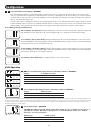
230V Operation
9
,
10
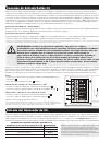
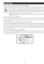
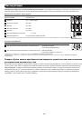
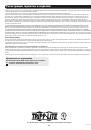
Select Low VAC Input Voltage Point for Switching to Battery—OPTIONAL*
Voltage
9, 10 Switch Position
180 VAC
Up, Up
170 VAC
Up, Down
160 VAC
Down, Up
150 VAC
Down, Down (factory setting)
11
Select High AC Input Voltage Point for Switching to Battery—OPTIONAL*
Voltage
Switch Position
270 VAC
Up
260 VAC
Down (factory setting)
Voltage
9, 10 Switch Position
180 VAC
Up, Up
170 VAC
Up, Down
160 VAC
Down, Up
150 VAC
Down, Down (factory setting)
230V Operation (APSX3024SW)
270 V
260 V
Select High AC Input Voltage Point for
Switching to Battery - OPTIONAL*
Voltage
Switch Position
270 VAC
Up
260 VAC
Down (factory setting)
11
9 10 11 12
270 V
260 V
Select High AC Input Voltage Point for
Switching to Battery - OPTIONAL*
Voltage
Switch Position
270 VAC
Up
260 VAC
Down (factory setting)
11
9 10 11 12
Select Low VAC Input Voltage Point for Switching to Battery
- OPTIONAL*
10
9
9 10 11 12
9 10 11 12
9 10 11 12
9 10 11 12
Voltage
9, 10 Switch Position
180 VAC
Up, Up
170 VAC
Up, Down
180 VAC
Down, Up
170 VAC
Down, Down (factory setting)
230V Operation (APSX6048VR model with Switch #4 in “Down” position)
Select Low VAC Input Voltage Point for Switching to Battery
10
9
9 10 11 12
9 10 11 12
9 10 11 12
9 10 11 12
208V Operation (APSX6048VR model with Switch #4 in “Up” position)
Select High AC Input Voltage Point for
Switching to Battery - OPTIONAL*
Voltage
Switch Position
245 VAC
Up
235 VAC
Down (factory setting)
11
245 V
235 V
9 10 11 12
Select Low VAC Input Voltage Point for Switching to Battery
- OPTIONAL*
10
9
Voltage
9, 10 Switch Position
175 VAC
Up, Up
165 VAC
Up, Down
175 VAC
Down, Up
165 VAC
Down, Down (factory setting)
9 10 11 12
9 10 11 12
9 10 11 12
9 10 11 12
Voltage
9, 10 Switch Position
180 VAC
Up, Up
170 VAC
Up, Down
160 VAC
Down, Up
150 VAC
Down, Down (factory setting)
230V Operation (APSX3024SW)
270 V
260 V
Select High AC Input Voltage Point for
Switching to Battery - OPTIONAL*
Voltage
Switch Position
270 VAC
Up
260 VAC
Down (factory setting)
11
9 10 11 12
270 V
260 V
Select High AC Input Voltage Point for
Switching to Battery - OPTIONAL*
Voltage
Switch Position
270 VAC
Up
260 VAC
Down (factory setting)
11
9 10 11 12
Select Low VAC Input Voltage Point for Switching to Battery
- OPTIONAL*
10
9
9 10 11 12
9 10 11 12
9 10 11 12
9 10 11 12
Voltage
9, 10 Switch Position
180 VAC
Up, Up
170 VAC
Up, Down
180 VAC
Down, Up
170 VAC
Down, Down (factory setting)
230V Operation (APSX6048VR model with Switch #4 in “Down” position)
Select Low VAC Input Voltage Point for Switching to Battery
10
9
9 10 11 12
9 10 11 12
9 10 11 12
9 10 11 12
208V Operation (APSX6048VR model with Switch #4 in “Up” position)
Select High AC Input Voltage Point for
Switching to Battery - OPTIONAL*
Voltage
Switch Position
245 VAC
Up
235 VAC
Down (factory setting)
11
245 V
235 V
9 10 11 12
Select Low VAC Input Voltage Point for Switching to Battery
- OPTIONAL*
10
9
Voltage
9, 10 Switch Position
175 VAC
Up, Up
165 VAC
Up, Down
175 VAC
Down, Up
165 VAC
Down, Down (factory setting)
9 10 11 12
9 10 11 12
9 10 11 12
9 10 11 12
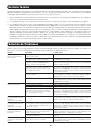
* Most of your connected appliances and equipment will perform adequately when your Inverter/Charger’s High AC Input Voltage Point and its Low AC Voltage Input Point is left in
the factory setting. However, if the unit frequently switches to battery power due to momentary high/low line voltage swings that would have little effect on equipment operation,
you may wish to adjust these settings. By increasing the High AC Voltage Point and/or decreasing the Low AC Voltage Point, you will reduce the number of times your unit
switches to battery due to voltage swings.
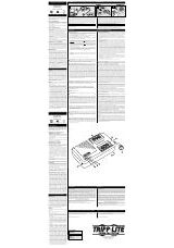
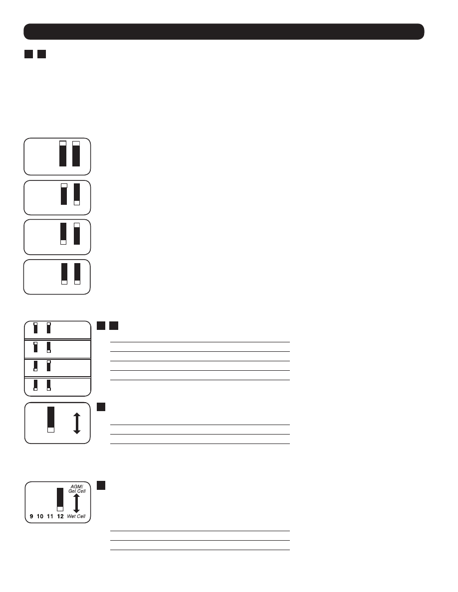
12
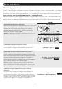
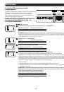
Select Battery Type—REQUIRED
CAUTION: The Battery Type DIP Switch setting must match the type of batteries you connect, or
your batteries may be degraded or damaged over an extended period of time. See “Battery
Selection,” for more information.
Battery Type
Switch Position
AGM/Gel Cell (Sealed) Battery Up
Wet Cell (Vented) Battery
Down (factory setting)
5 6 7 8
5 6 7 8
5 6 7 8
If your unit is equipped with DIP switches 7 and 8, they may be used to select other AC
input current sharing settings.
5 6 7 8