7
Configuration
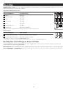
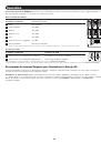
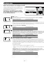
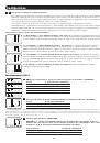
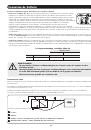
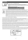
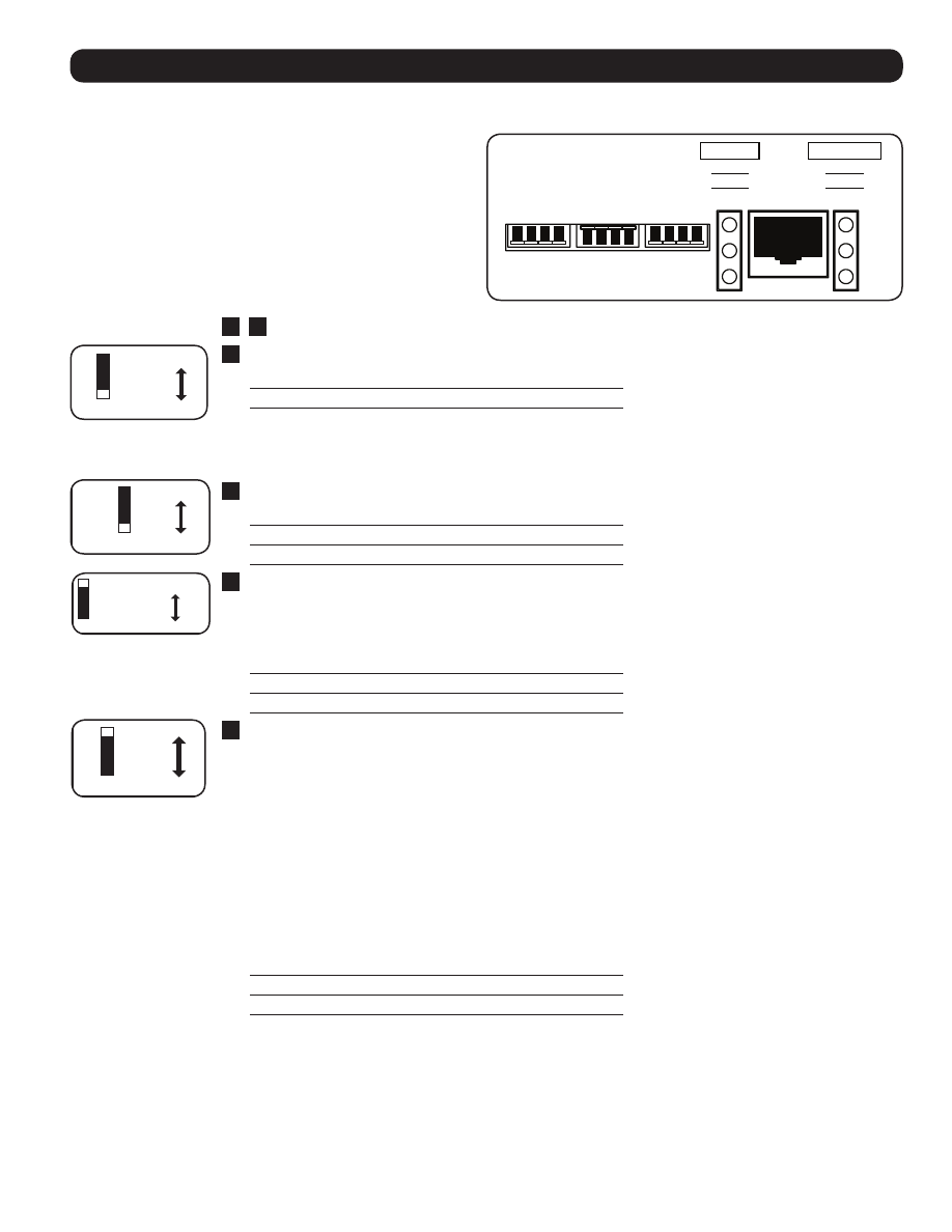
Set Configuration DIP Switches
Using a small tool, set the Configuration DIP Switches (located on
the front panel of your unit, see diagram) to optimize Inverter/
Charger operation depending on your application.
WARNING: MAKE SURE THE UNIT IS TURNED OFF
BEFORE CHANGING DIP SWITCH SETTINGS.
208 V
230 V
60 Hz
50 Hz
Faster
Slower
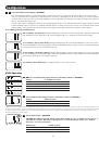
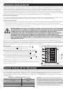
Select Line Voltage - REQUIRED
(APSX6048VR model only)
Voltage
Switch Position
208 VAC
Up
230 VAC
Down (factory setting)
4
Select Frequency - REQUIRED
Frequency
Switch Position
60 Hz
Up
50 Hz
Down (factory setting)
3
Select Line Connect Relay Transfer Time - OPTIONAL
Transfer Time
Switch Position
1/2 Cycle Transfer Time Up
1 Cycle Transfer Time
Down (factory setting)
2
Not Used
1
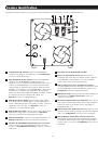
BATTERY
HIGH
MED
LOW
OPERATION
LINE
INV
LOAD
REMOTE
CONTROL
CONFIGURATION DIP SWITCHES
(SEE MANUAL OR TOP OF UNIT FOR INSTRUCTIONS)
1 2 3 4
5 6 7 8
9 10 11 12
1 2 3 4
1 2 3 4
1 2 3 4
Note: The Inverter/Charger’s default transfer time setting is 1 cycle, which provides
optimal protection for standard loads in areas with frequent outages. If you will use
the Inverter/Charger to support computers or other sensitive electronic equipment
loads, set the transfer time to ½ cycle (switch #2 UP) to ensure uninterrupted operation
when the Inverter/Charger transfers to battery power.
208 V
230 V
60 Hz
50 Hz
Faster
Slower
Select Line Voltage - REQUIRED
(APSX6048VR model only)
Voltage
Switch Position
208 VAC
Up
230 VAC
Down (factory setting)
4
Select Frequency - REQUIRED
Frequency
Switch Position
60 Hz
Up
50 Hz
Down (factory setting)
3
Select Line Connect Relay Transfer Time - OPTIONAL
Transfer Time
Switch Position
1/2 Cycle Transfer Time Up
1 Cycle Transfer Time
Down (factory setting)
2
Not Used
1
BATTERY
HIGH
MED
LOW
OPERATION
LINE
INV
LOAD
REMOTE
CONTROL
CONFIGURATION DIP SWITCHES
(SEE MANUAL OR TOP OF UNIT FOR INSTRUCTIONS)
1 2 3 4
5 6 7 8
9 10 11 12
1 2 3 4
1 2 3 4
1 2 3 4
Note: The Inverter/Charger’s default transfer time setting is 1 cycle, which provides
optimal protection for standard loads in areas with frequent outages. If you will use
the Inverter/Charger to support computers or other sensitive electronic equipment
loads, set the transfer time to ½ cycle (switch #2 UP) to ensure uninterrupted operation
when the Inverter/Charger transfers to battery power.
1
,
4
Not Used
2
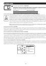
Select Line Connect Relay Transfer Time—OPTIONAL
Transfer Time
Switch Position
½ Cycle Transfer Time
Up
1 Cycle Transfer Time
Down (factory setting)
NOTE:
The Inverter/Charger’s default transfer time setting is 1 cycle, which provides optimal protection for standard loads in areas with
frequent outages. If you will use the Inverter/Charger to support computers or other sensitive electronic equipment loads, set the transfer
time to ½ cycle (switch #2 UP) to ensure uninterrupted operation when the inverter/Charger transfers to battery power.
3
Select Frequency—REQUIRED
Frquency
Switch Position
60 Hz
Up (factory setting)
50 Hz
Down
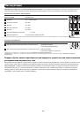
5
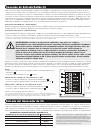
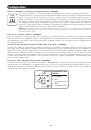
Select Battery Charger Amp Setting
CAUTION: When switching to the High Charge Amp setting, the user must ensure that the amp hour
capacity of their battery system exceeds the amperage of the High Charge Amp setting or the
batteries may be damaged or degraded.
Battery Charger
Switch Position
Low Charge Amps (23A) Up (factory setting)
High Charge Amps (90A) Down
6
Select Equalize Battery Charge—OPTIONAL
Switch this DIP switch to the down position for 3 seconds to begin the process of equalizing the charge
state of your battery’s cells by time-limited overcharge of all cells. This can extend the useful life of certain
types of batteries; consult with your battery’s manufacturer to determine if your batteries could benefit from
this process. The charge equalization process is automatic; once started, it can only be stopped by removing
the input power.
Setting Procedure
• Move to “Equalize” (DOWN) postition for 3 seconds.
• Move to “Reset” (UP) postition and leave it there. This is the factory default setting.
CAUTION: Do not leave DIP switch #6 in the down position after beginning process. Battery charge
equalization should only be performed in strict accordance with the battery manufacturer’s
instructions and specifications.
Battery Charge
Switch Position
Reset
Up (factory setting)
Equalize
Down (3 seconds)
208 V
230 V
60 Hz
50 Hz
Faster
Slower
Select Line Voltage - REQUIRED
(APSX6048VR model only)
Voltage
Switch Position
208 VAC
Up
230 VAC
Down (factory setting)
4
Select Frequency - REQUIRED
Frequency
Switch Position
60 Hz
Up
50 Hz
Down (factory setting)
3
Select Line Connect Relay Transfer Time - OPTIONAL
Transfer Time
Switch Position
1/2 Cycle Transfer Time Up
1 Cycle Transfer Time
Down (factory setting)
2
Not Used
1
BATTERY
HIGH
MED
LOW
OPERATION
LINE
INV
LOAD
REMOTE
CONTROL
CONFIGURATION DIP SWITCHES
(SEE MANUAL OR TOP OF UNIT FOR INSTRUCTIONS)
1 2 3 4
5 6 7 8
9 10 11 12
1 2 3 4
1 2 3 4
1 2 3 4
Note: The Inverter/Charger’s default transfer time setting is 1 cycle, which provides
optimal protection for standard loads in areas with frequent outages. If you will use
the Inverter/Charger to support computers or other sensitive electronic equipment
loads, set the transfer time to ½ cycle (switch #2 UP) to ensure uninterrupted operation
when the Inverter/Charger transfers to battery power.
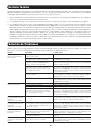
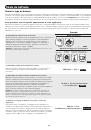
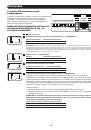
“Reset”
“Equalize”
Low Charge Amp
High Charge Amp
1
Select Equalize Battery Charge - OPTIONAL
Battery Charge
Switch Position
Reset
Up (factory setting)
Equalize
Down (3 seconds)
Battery Charger
Switch Position
Low Charge Amps (23A)
Up (factory setting)
High Charge Amps (90A)
Down
6
Select Battery Charger Amp Setting
5
7
8
9
Switch this DIP switch to the down position for 3 seconds to begin the
process of equalizing the charge state of your battery’s cells by
time-limited overcharge of all cells. This can extend the useful life of
certain types of batteries; consult with your battery’s manufacturer to
determine if your batteries could benefit from this process. The charge
equalization process is automatic; once started, it can only be stopped
by removing the input power.
Setting Procedure
• Move to “Equalize” (DOWN) postition for 3 seconds.
• Move to “Reset” (UP) postition and leave it there. This is the factory default setting.
CAUTION: Do not leave DIP switch #6 in the down position after beginning process. Battery charge
equalization should only be performed in strict accordance with the battery manufacturer’s instructions
and specifications.
CAUTION: When switching to the High Charge Amp setting, the user
must ensure that the amp hour capacity of their battery system exceeds
the amperage of the High Charge Amp setting or the batteries may be
damaged or degraded.
Not Used
5 6 7 8
5 6 7 8